
Degasser applied to analysis of dissolved gas in oil by photoacoustic spectroscopy principle

A technology of dissolving gas in oil and degassing device, which is applied to liquid degassing, separation methods, chemical instruments and methods, etc. Longevity, avoidance of pipeline jams, cost reduction effect

Active Publication Date: 2015-05-20
STATE GRID CORP OF CHINA +3
View PDF9 Cites 11 Cited by
  • Summary
  • Abstract
  • Description
  • Claims
  • Application Information

AI Technical Summary

Problems solved by technology

The headspace degassing principle has a low degassing rate, and there is a risk of blowing air bubbles into the transformer in the positive pressure headspace; the degassing equilibrium time of the polymer permeable membrane is long, and the diaphragm is easily damaged; the vacuum degassing rate is high, and the balance The time is short, the degassing device involved in this patent is the principle of vacuum degassing
[0005] Chinese Patent Application No. 201310124234.2 describes the principle of a degassing device. This degassing device is applied to a gas chromatography device with a carrier gas, but not suitable for a photoacoustic spectroscopy device, and does not have a two-way safe oil return function.

Method used


Image

  • Degasser applied to analysis of dissolved gas in oil by photoacoustic spectroscopy principle
  • Degasser applied to analysis of dissolved gas in oil by photoacoustic spectroscopy principle
  • Degasser applied to analysis of dissolved gas in oil by photoacoustic spectroscopy principle

Examples


Embodiment Construction

[0023] The technical solution of the present invention will be further described in detail below in conjunction with the accompanying drawings of the description.

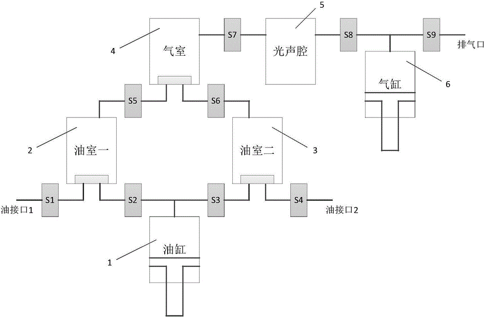
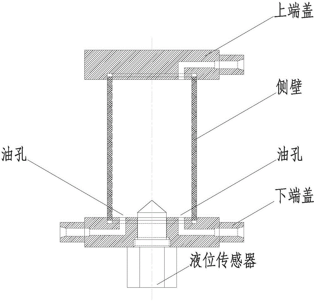
[0024] Such as figure 1 As shown, the degassing device of the present invention includes oil cylinder 1, oil chamber 2, 3, air chamber 4, photoacoustic chamber 5, cylinder 6, solenoid valves S1~S9 and electronic control equipment (not shown in the figure) that controls the action of each solenoid valve draw). The oil hole on one side of the lower end of the oil chamber is connected to the transformer oil tank through the solenoid valve S1, and the oil hole on the other side is connected to the oil cylinder through the solenoid valve S2; the oil hole on the lower side of the second oil chamber is connected to the oil cylinder through the solenoid valve S3, and the other The side oil hole is connected to the transformer oil tank through the solenoid valve S4; the opening on one side of the lower end of the air chamb...


PUM


Abstract

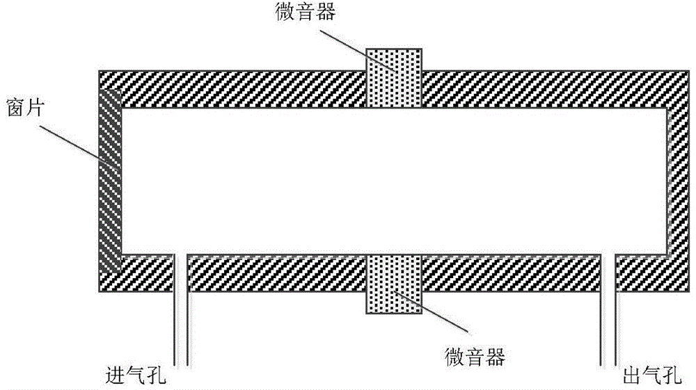
The invention discloses a degasser applied to analysis of a dissolved gas in oil by a photoacoustic spectroscopy principle so as to separate oil and gas of transformer insulation oil. The degasser is mainly composed of an oil cylinder, a gas cylinder, a gas chamber, oil chambers and a photoacoustic cavity. Characteristic gas separated by vacuum degassing can be transferred into the photoacoustic cavity to be used in photoacoustic spectrometry. The oil chambers, the gas chamber and the photoacoustic cavity of the degasser are special chamber components, wherein each oil chamber is of a double-hole bottom-cover structure, and oil can be returned safely in cooperation with a liquid level sensor. Two symmetrical oil chambers are arranged on the degasser to achieve the functions of dual-direction oil return and oil channel cleaning; meanwhile, single-point oil sample collection can be prevented, and the multi-point circulation collection of the oil sample can be realized.

Description

technical field [0001] The invention belongs to the field of on-line monitoring of intelligent substations. The invention provides a degassing device applied to the analysis of dissolved gas in oil based on the principle of photoacoustic spectroscopy. The vacuum degassing principle can be used to effectively separate the dissolved gas in transformer insulating oil. Background technique [0002] Power transformers are one of the most important equipment in substations, and transformer insulation failures often bring huge economic losses. In traditional substations, preventive tests are generally used to judge the insulation status of transformers. The preventive tests performed regularly have problems of over- and under-maintenance at the same time, which is no longer suitable for the increasing scale of the power grid. In the intelligent substation, the insulation state of the transformer can be reflected in real time through the online monitoring device, and the state-of-th...

Claims


Application Information

Patent Timeline
IPC IPC(8): B01D19/00
Inventor 李征袁帅任雁铭杨宁黄昕是艳杰唐喜
Owner STATE GRID CORP OF CHINA
Learn More