An automatic clamping method for high-voltage grounding wire

A technology of automatic clamping and grounding wires, which is applied in the direction of clamping/spring connection, clamp connection conductor connection, multi-core cable end parts, etc., which can solve the problems of inconvenient operation and wire falling off, so as to reduce the burden on personnel and improve Work efficiency, reduce the effect of manual labor intensity

Active Publication Date: 2017-10-17
STATE GRID CORP OF CHINA +2
View PDF16 Cites 0 Cited by
  • Summary
  • Abstract
  • Description
  • Claims
  • Application Information

AI Technical Summary

Problems solved by technology

In the current design, the handle is not only the support end but also the clamping and rotating transmission rod, which is inconvenient in actual operation and has the disadvantage that it is easy to fall off from the wire and busbar, especially on the long ground wire of the operating rod.

Method used


Image

  • An automatic clamping method for high-voltage grounding wire
  • An automatic clamping method for high-voltage grounding wire
  • An automatic clamping method for high-voltage grounding wire

Examples


Embodiment 1

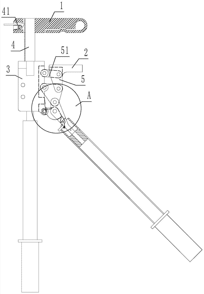
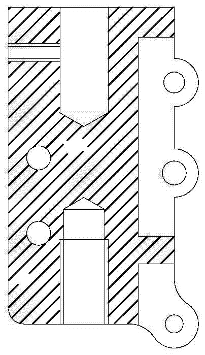
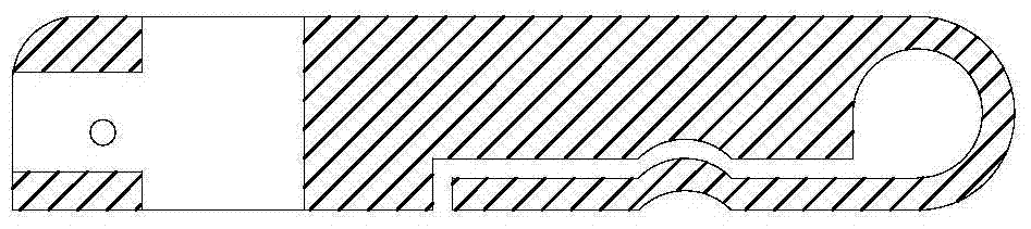
[0028] An automatic clamping method for high-voltage grounding wires provides an automatic clamping device for high-voltage grounding wires, which comprises an upper wire clamping block 1, a lower wire clamping block 2, and a connecting block 3. The connecting block is provided with an upward unilateral side For the rack 4, the serrations of the single-sided rack are facing outward, the upper thread clamping block passes through the single-sided rack, and the side of the upper thread clamping block that passes through the serrations of the single-sided rack is provided with tooth claw holes and the teeth A toothed claw 41 is installed in the claw hole to cooperate with the rack to realize the positioning of the two. A six-bar mechanism 5 is provided on the connecting block. The six-bar mechanism includes three connecting rods 51 and two connecting rods. 52. Three connecting rods are distributed on the connecting block from top to bottom. The first connecting rod, the second conn...


PUM


Abstract

The invention discloses an automatic clamping method of a high voltage grounding wire. The method is characterized in that an upward single-side rack upper wire clamping block is arranged on a connecting block and passes through a single-side rack; a six-rod mechanism comprises three connecting frame rods and two connecting rods; the three connecting frame rods are distributed from top to bottom on the connecting block; the first connecting frame rod, the second connecting frame rod and the corresponding first connecting rod form a parallelogram movement pair which drives the first connecting rod to move up and down by reciprocating; a lower wire clamping block directly adopts the first connecting rod as a connecting block or is connected to the first connecting rod; the lower wire clamping block and the upper wire clamping block are equipped with clamping surfaces which are parallel to each other; a connecting device which can be connected with an insulating operating rod is arranged on the second connecting rod which is connected with the second connecting frame rod and the third connecting frame rod; a stopping device is arranged between the third connecting frame rod and the second connecting rod. With the adoption of the method, an efficient clamping torque can be provided, so that a ground wire can be mounted according to the standard; meanwhile, the labor intensity of operators in ground wire mounting can be greatly reduced, and the working efficiency can be increased.

Description

Technical field [0001] The invention relates to a clamping device, in particular to an automatic clamping method for high-voltage grounding wires. Background technique [0002] At present, high-voltage ground wires are used in substations, and the ground wire ends have different structures, and the openings of the ground ends are large or small, and the adaptability is not good. Sometimes in order to meet the requirements of installing ground wires at different locations, the same substation needs to be equipped with several types of ground wires from different manufacturers. The grounding wire operation method is manual clamping, which has the problem of insufficient clamping torque and varying with the operating force. In the current design, the handle is not only a supporting end but also a transmission rod for clamping rotation, which is inconvenient in actual operation and has the disadvantage of being easy to fall off the wire and busbar, especially on the long ground wire...

Claims


Application Information

Patent Timeline
Patent Type & Authority Patents(China)
IPC IPC(8): H01R43/027H01R11/11H01R4/28
CPCH01R4/28H01R11/11H01R43/027
Inventor 陈钊张丰谢聿琳郭晓杭
Owner STATE GRID CORP OF CHINA
Why Eureka
Try Eureka