Variable-diameter stabilizer capable of being controlled on ground
A stabilizer and ground technology, applied in drilling equipment, earth-moving drilling, drill pipe, etc., can solve the problems of reducing drilling aging, scraping, long adjustment period, etc., to improve drilling aging, simple device structure and convenient operation. Effect
- Summary
- Abstract
- Description
- Claims
- Application Information
AI Technical Summary
Problems solved by technology
Method used
Image
Examples
Embodiment 1
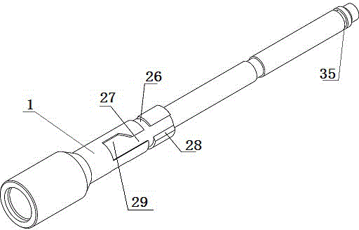
[0041] This embodiment provides a variable diameter stabilizer that can be controlled on the ground, such as Figures 1 to 5 As shown, it includes a tubular casing, the casing is equipped with a central shaft 1, and the casing is composed of an upper casing 2, a middle casing 3 and a lower casing 4 connected in sequence,
[0042] The upper part of the central shaft 1 is provided with a self-locking groove, and the middle part of the central shaft 1 is fixed with a tapered sleeve 5;
[0043] The upper part of the upper housing 2 is provided with a lock block square hole 23, and a self-locking device is installed in the lock block square hole 23. The inner end of the self-locking device corresponds to the self-locking groove on the central axis 1; the lower part of the upper housing 2 is along the circumferential direction There are a plurality of cylindrical holes 24 distributed in the axial direction. The cylindrical holes 24 are equipped with stabilizing columns 6 , and the i...
Embodiment 2
[0049] On the basis of Embodiment 1, the self-locking device in the lock block square hole 23 in this embodiment is made up of a self-lock block 16, a self-lock spring 17, a spring pressing plate 18 and a fastening screw 19, and the fastening screw 19 presses the spring pressing plate 18 is fixed in the square hole 23 of the locking block, the self-locking spring 17 and the self-locking block 16 are positioned at the inner side of the spring pressing plate 18, and the two ends of the self-locking spring 17 are respectively fixed on the spring pressing plate 18 and the self-locking block 16, and the self-locking block 16 The bottom end face is arc-shaped, such as Figure 11As shown, the self-locking block 16 is a cube structure, one end face is arc-shaped, one corner of the arc-shaped end face is cut off, and the other end face is provided with a cylindrical spring hole for installing the self-locking spring 17 .
[0050] A rectangular protrusion 25 is also provided on the inne...
Embodiment 3
[0056] In Embodiment 1, the stabilizing post 6 will move radially along with the axial movement of the tapered sleeve 5. In this embodiment, as Image 6 with Figure 7 As shown, the upper end surface of the stabilizing column 6 is an arc surface, and the lower end surface is a conical plane with a dovetail groove 30 .
[0057] In this embodiment, the dovetail groove 30 and the dovetail block track 31 are used to cooperate to connect the stabilizing post 6 to the tapered sleeve 5. With the axial movement of the tapered sleeve 5, the stabilizing post 6 moves on the tapered surface. The dovetail block track 31 on the sleeve 5 slides and moves radially.
[0058] In this embodiment, the tapered sleeve 5 may also be spliced by several tapered sleeves fitted on the central shaft 1 sequentially in the axial direction.
[0059] Further, the plurality of cylindrical holes 24 are distributed in a helical shape along the axial direction at the lower part of the upper casing 2 , and th...
PUM
 Abstract
Description
Claims
Application Information
 - R&D
- Intellectual Property
- Life Sciences
- Materials
- Tech Scout
- Unparalleled Data Quality
- Higher Quality Content
- 60% Fewer Hallucinations
Browse by: Latest US Patents, China's latest patents, Technical Efficacy Thesaurus, Application Domain, Technology Topic, Popular Technical Reports.
© 2025 PatSnap. All rights reserved.Legal|Privacy policy|Modern Slavery Act Transparency Statement|Sitemap|About US| Contact US: help@patsnap.com


