Bathroom floor drain

A floor drain and bathroom technology, which is applied in the field of bathroom floor drains, can solve the problems of easy clogging of hair and inconvenient cleaning, and achieve the effect of not easy to return the smell, overcome easy clogging of hair, and good cleaning effect

Inactive Publication Date: 2015-05-06
CHONGQING CONCAST SANITARY WARE
View PDF0 Cites 10 Cited by
  • Summary
  • Abstract
  • Description
  • Claims
  • Application Information

AI Technical Summary

Problems solved by technology

[0005] The bathroom floor drain adopting the above technical solution has the following advantages: when drainage is required, the sealing cover is removed, and the ground water enters the filter chamber, and the ground is not easy to accumulate water, and the filter plate traps impurities and fallen hair on the surface of the filter plate, and the filter plate The final water enters the lower fixed seat, and then is discharged from the water outlet at the bottom of the fixed seat. Since the movable shell and the filter plate are integrally buckled on the fixed seat, it can also be directly removed for cleaning. Further, the through groove and movable The rod is set so that when the movable rod is pulled out, the cleaning liquid can be injected from the through groove, and then the movable rod is blocked. Under the action of the downward force, the movable rod is helpful to push the cleaning liquid into the floor drain for good cleaning As a result, the floor drain is not easy to return to smell, and the bathroom floor drain adopting the technical solution of the present invention overcomes the technical problems of easy clogging of hair and inconvenient cleaning in the prior art

Method used


Image

  • Bathroom floor drain

Examples


Embodiment Construction

[0011] Below in conjunction with accompanying drawing and embodiment the technical solution of the present invention is further described:

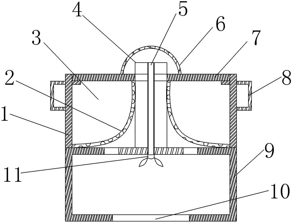
[0012] Such as figure 1 As shown: the present invention provides a bathroom floor drain, which includes a fixed seat 9 and a movable housing 1 buckled on the fixed seat 9, a water outlet 10 is provided at the bottom of the fixed seat 9, and a hole is provided on the upper part of the fixed seat 9, which can be moved The upper part of the housing 1 is open, and a column-shaped fixed block 4 is arranged in the middle of the fixed seat 9. A through groove is arranged in the middle of the fixed block 4, and a movable rod 5 is arranged in the through groove, and a filter plate is connected to the movable housing 1. 2. The filter plate 2 and the movable housing 1 form a filter chamber 3, and a sealing cover 7 is fastened above the filter chamber 3. One end of the fixed block 4 close to the water outlet is provided with a blade 11, the blade 11...


PUM


Abstract

The invention relates to the technical field of bathroom equipment, in particular to a bathroom floor drain. The bathroom floor drain comprises a fixing seat and a movable shell. The movable shell is installed on the fixing seat in a buckling mode, a water outlet is formed in the bottom of the fixing seat, a hole is formed in the upper portion of the fixing seat, an opening is formed in the upper portion of the movable shell, a column-shaped fixing block is arranged in the middle of the fixing seat, a through groove is formed in the middle portion of the fixing block, a movable rod is arranged in the through groove, filtering plates are connected with the movable shell, the filtering plates and the movable shell form a filtering chamber, and a sealing cover is installed on the upper portion of the filtering chamber in a bucking mode. According to the technical scheme, the bathroom floor drain is not prone to be blocked, convenient to clean, and not prone to return smell.

Description

technical field [0001] The invention relates to the technical field of sanitary equipment, in particular to a sanitary floor drain. Background technique [0002] Floor drains are common sanitary components in daily life, and it is often necessary to install floor drains for drainage in toilets, bathrooms or balconies. The floor drain frame and the floor drain cover in the traditional floor drain are both flat and parallel to the ground after installation, which is not conducive to the smooth discharge of ground water, and the ground is prone to water accumulation. Moreover, the common floor drains installed under the bathroom or bathing pool are often blocked due to the accumulation of shedding hair and the like, and it is very troublesome to clean each time. Contents of the invention [0003] The technical problem to be solved by the present invention is to provide a bathroom floor drain which is not easy to block, easy to clean, and not easy to return to smell. [0...

Claims


Application Information

Patent Timeline
Patent Type & Authority Applications(China)
IPC IPC(8): E03F5/04
CPCE03F5/0407E03F5/0408E03F5/14E03F9/00
Inventor 唐其云
Owner CHONGQING CONCAST SANITARY WARE
Why Eureka
Try Eureka