Method for producing biogas by use of U-shaped generation system with multiple partitions for promoting biogas slurry turbulence

A horseshoe-shaped, biogas slurry technology, applied in the field of biogas fermentation system, can solve the problems of uneven distribution of bacteria, poor biogas slurry convection effect, short fermentation efficiency route, etc., to reduce difficulty, reduce operation difficulty, facilitate feeding and discharging the effect of

Inactive Publication Date: 2015-05-06
李俊
View PDF0 Cites 0 Cited by
  • Summary
  • Abstract
  • Description
  • Claims
  • Application Information

AI Technical Summary

Problems solved by technology

[0004] In order to solve the deficiencies of the prior art, the technical problem to be solved by the present invention is that the fermentation efficiency route of the traditional biogas digester is short, the fermentation efficiency is low, and the biogas slurry convection effect is poor, resulting in uneven distribution of bacteria, etc.

Method used


Image

  • Method for producing biogas by use of U-shaped generation system with multiple partitions for promoting biogas slurry turbulence
  • Method for producing biogas by use of U-shaped generation system with multiple partitions for promoting biogas slurry turbulence
  • Method for producing biogas by use of U-shaped generation system with multiple partitions for promoting biogas slurry turbulence

Examples


Embodiment Construction

[0030] The following describes the technical solutions in the embodiments of the present invention clearly and completely with reference to the accompanying drawings in the embodiments of the present invention. Obviously, the described embodiments are only a part of the embodiments of the present invention, not all the embodiments. Based on the embodiments of the present invention, all other embodiments obtained by those of ordinary skill in the art without creative work shall fall within the protection scope of the present invention.

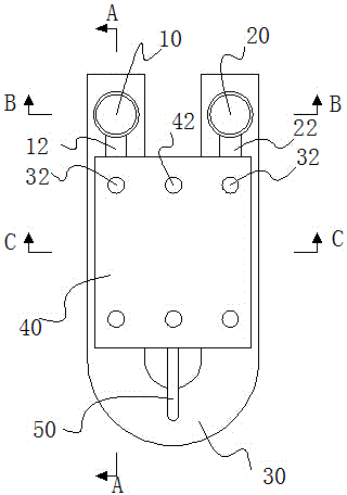
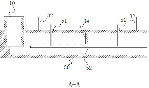
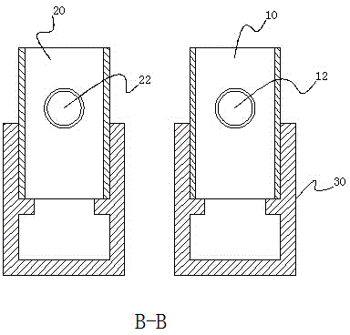
[0031] Such as figure 1 As shown, a horseshoe-shaped super-efficient biogas generation system with several partitions to promote turbulent flow of biogas slurry is mainly composed of a feed pipe 10, a discharge pipe 20, a fermentation pipe 30, and a hydraulic chamber 40. The fermentation pipe 30 is a U-shaped fermentation pipe. The cross-sectional shape of the U-shaped fermentation pipe can be original, rectangular, elliptical and other geometric s...


PUM


Abstract

The invention discloses a method for producing biogas by use of a U-shaped generation system with multiple partitions for promoting biogas slurry turbulence. The method comprises the following steps: fermentation raw materials are poured into a U-shaped fermentation pipeline via a feed pipe and fermented in the U-shaped fermentation pipeline to generate biogas; the biogas is gathered in a space between the sidewall of the feed pipe and the sidewall of a discharge pipe; the biogas occupies the space in the fermentation pipeline and squeezes the biogas slurry in the fermentation pipeline to force the biogas slurry to flow into the feed pipe and the discharge pipe and then flow into a water pressure chamber via a discharge pipe drain pipe; the biogas stored in the fermentation pipeline is utilized to lead to the reduction of the biogas pressure in the fermentation pipeline, so that the biogas slurry stored in the water pressure chamber flows back into the feed pipe via a feed pipe drain pipe in one direction and then flows back into the fermentation pipeline via the discharge pipe drain pipe, and when the liquid level of the biogas slurry in the water pressure chamber is lower than the lowest point position of the discharge pipe drain pipe, the biogas slurry in the water pressure chamber is only capable of flowing into the feed pipe via the feed pipe drain pipe in one direction, and therefore, the circulating flow of the biogas slurry is completed; the biogas is continuously generated and utilized according to the method of the steps A and B, and the circulating flow of the biogas slurry is promoted.

Description

Technical field [0001] The invention relates to an anaerobic fermentation device, in particular to a biogas fermentation system. Background technique [0002] The working principle of the traditional biogas digester is that when biogas is produced in the digester, the biogas in the gas storage room continues to increase, and the pressure continues to increase, forcing the liquid level in the main tank to drop, squeezing out a part of the material liquid into the water pressure room. When people turn on the stove, the pressure in the biogas digester gradually drops, and the material liquid in the hydraulic pressure room continues to flow back to the main tank. In this way, gas is continuously produced and used, so that the pressure balance between the fermentation room and the discharge room is always maintained. [0003] The traditional biogas digester has a short fermentation route, poor fluidity of the biogas slurry, and uneven distribution of strains, which causes the gas produc...

Claims


Application Information

Patent Timeline
IPC IPC(8): C12M1/107C12P5/02C02F11/04
CPCC12M21/04C12M23/06C12M29/00Y02E50/30
Inventor 李俊
Owner 李俊
Why Eureka
Try Eureka