Moving lifting device

A technology of lifting device and moving mechanism, applied in the direction of lifting device, lifting frame, etc., can solve the problems of inconvenient handling and movement, unable to adapt to uneven ground, etc., and achieve the effects of simple structure, reduced thickness and convenient movement.

Active Publication Date: 2015-05-06
THE SECOND CONSTR ENG CO LTD CCSEB
View PDF5 Cites 5 Cited by
  • Summary
  • Abstract
  • Description
  • Claims
  • Application Information

AI Technical Summary

Problems solved by technology

[0004] Based on this, it is necessary to provide a mobile lifting device with convenient movement, simple structure and self-adaptive adjustment balance for the problems of inconvenient handling and movement of ladders and mobile lifting devices in the prior art and inability to adapt to uneven ground

Method used


Image

  • Moving lifting device
  • Moving lifting device
  • Moving lifting device

Examples


Embodiment Construction

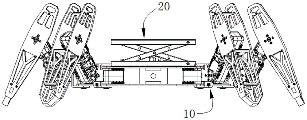
[0032] see figure 1 , which is a side view of a mobile lifting device according to a preferred embodiment of the present invention.

[0033] The mobile lifting device includes a moving mechanism 10 and a lifting mechanism 20 .

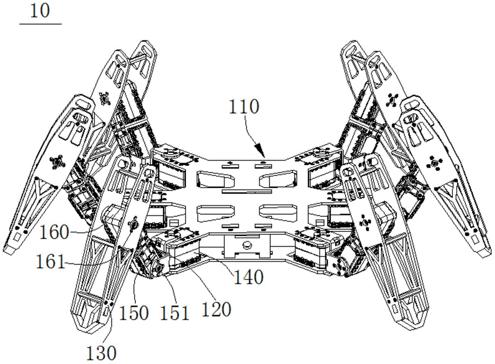
[0034] Please also refer to figure 2 , which is figure 1 The structural diagram of the moving mechanism 10. The moving mechanism 10 includes: a support plate 110 , a connecting portion 120 and a claw 130 . Six first motors 140 are arranged at intervals on a side of the support plate 110 , and the rotation axes of the first motors 140 are perpendicular to the support plate 110 . The connecting part 120 is drivingly connected with the rotating shaft of the first motor 140, the connecting part 120 is drivingly connected with the second motor 150, the rotating shaft 151 of the second motor 150 is perpendicular to the rotating shaft of the first motor 140, and the second motor 150 is fixed with The third motor 160 , the rotation axis 161 of the third ...


PUM


Abstract

The invention relates to a moving lifting device which comprises a moving mechanism and a lifting mechanism. The moving mechanism comprises a supporting plate, connecting parts and supporting claws. Multiple first motors connected with the connecting parts are arranged on the supporting plate, and rotating shafts of the first motors are perpendicular to the supporting plate. The connecting parts are connected with second motors, rotating shafts of the second motors are perpendicular to the rotating shafts of the first motors, third motors connected with the supporting claws are fixed on the second motors, and rotating shafts of the third motors is parallel to the rotating shafts of the second motors. The lifting mechanism comprises an underbed, two fork-shaped articulation pieces, a cylinder and a foot rack. The underbed is arranged on the supporting plate, the two ends of each fork-shaped articulation piece are connected with the underbed in a hinged mode, the other two ends of each fork-shaped articulation piece are connected with the foot rack in a slidable mode, and the cylinder drives the two fork-shaped articulation pieces to drive the foot rack to be lifted. The moving mechanism drives the supporting claws to move through motors, and drives the two fork-shaped articulation pieces to drive the foot rack to rise and fall through the cylinder. The moving lifting device is convenient to move, simple in structure, and capable of automatically adapting and adjusting balance.

Description

technical field [0001] The invention relates to a mobile lifting device. Background technique [0002] When painting, drilling, wiring and other operations at high places in the blank room, straight ladders or ladders are usually erected. Due to the uneven ground in the room, the ladders are often placed unstable, easily tilted and collapsed, causing injuries to workers. During the construction process, it is often necessary to move the location, and personnel must get off the straight ladder or the ladder and carry the heavy straight ladder or the ladder to the corresponding position, which makes the moving operation cumbersome and inconvenient to carry. [0003] The traditional mobile lifting device is usually mounted on a roller car, which is bulky and inconvenient to move and carry. In addition, when the roller car is parked on uneven ground, pads need to be placed on the bottom of the car to adjust the position of the lifting device. Balanced state, the process is cumb...

Claims


Application Information

Patent Timeline
Patent Type & Authority Applications(China)
IPC IPC(8): B66F7/08B66F7/28
CPCB66F7/085B66F7/28
Inventor 张晶
Owner THE SECOND CONSTR ENG CO LTD CCSEB
Why Eureka
Try Eureka