Constant force lifting device
A lifting device and constant force technology, which is applied in hoisting devices, supporting machines, mechanical equipment, etc., can solve problems such as the inability to realize constant force lifting of fixed brackets, and achieve the effect of prolonging the service life and expanding the scope of use
- Summary
- Abstract
- Description
- Claims
- Application Information
AI Technical Summary
Problems solved by technology
Method used
Image

Examples
Embodiment 1
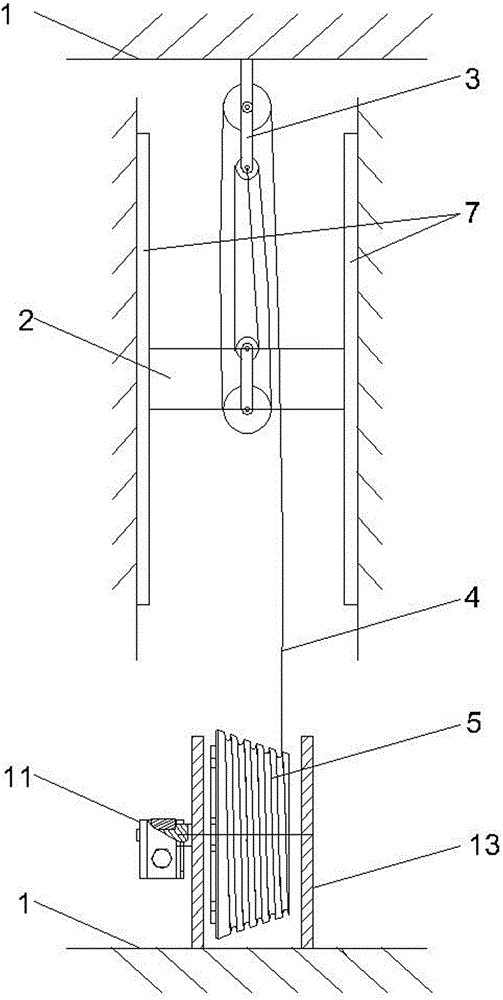
[0034] The constant force lifting device of this embodiment includes a support 1, a weight frame 2, a pulley block 3, a traction line 4, a power structure, and a power adjustment device.
[0035]Described pulley block 3 is formed by matching large and small two fixed pulley blocks and large and small two movable pulley blocks. The parts of pulley block are formed with prior art, and main part is pulley, also has some auxiliary parts such as central shaft, connecting support 1. The large and small fixed pulley blocks are fixed together through the same connecting bracket 1, and are fixed on the top of the support 1; the large and small movable pulley blocks are fixed together through the same connecting bracket 1. The size of the pulleys in the large fixed pulley block is the same as that in the large movable pulley block; the size of the pulleys in the small fixed pulley block is the same as that in the small movable pulley block.
[0036] The weight frame 2 is connected to t...
Embodiment 2
[0041] The constant force lifting device of this embodiment includes a support 1, a weight frame 2, a pulley block 3, a traction line 4, a power structure, and a power adjustment device.
[0042] Described pulley block 3 is formed by matching a fixed pulley block and a movable pulley block. The parts of pulley block are formed with prior art, and main part is pulley, also has some auxiliary parts such as central shaft, connecting support 1. The size of the pulleys in the fixed pulley block is the same as that in the movable pulley block.
[0043] The weight frame 2 is connected to the moving pulley block, and its two sides are slidably connected to two parallel guide rails 7 arranged on the front of the support 1, and the guide rails 7 are ball guide rails.
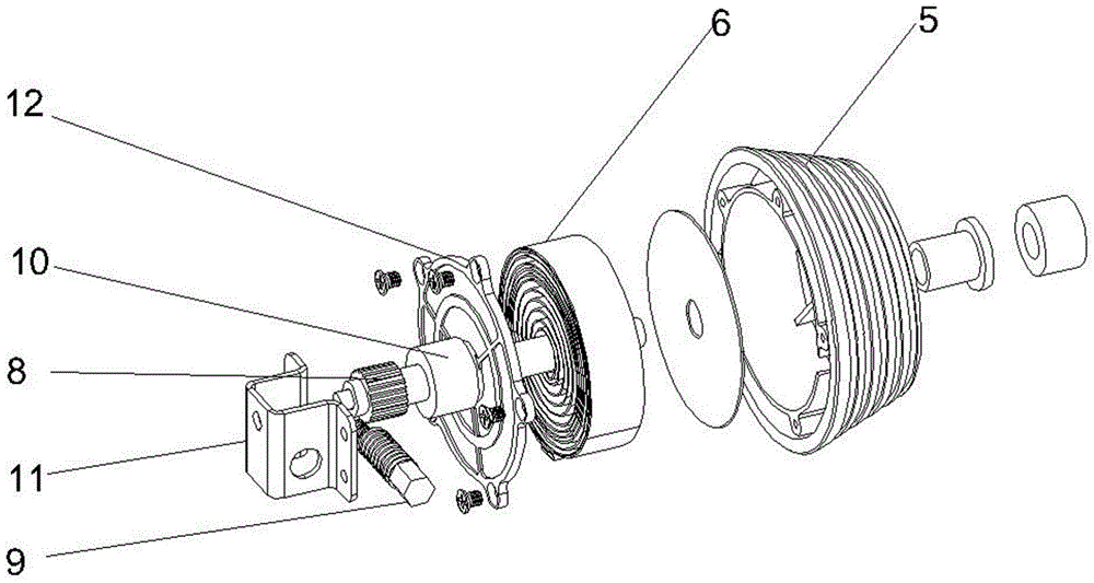
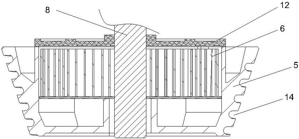
[0044] The power structure includes a tower-shaped winding disk 5 and a contact-type planar scroll spring 6 arranged inside the tower-shaped winding disk 5 . The tower-shaped winding reel 5 is fixed on the lower part of...
Embodiment 3
[0048] The constant force lifting device of this embodiment includes a support 1, a weight frame 2, a pulley block 3, a traction line 4, a power structure, and a power adjustment device.
[0049] Described pulley block 3 is formed by matching large, medium and small three fixed pulley blocks and large, medium and small three movable pulley blocks. The parts of pulley block are formed with prior art, and main part is pulley, also has some auxiliary parts such as central shaft, connecting support 1. Large, medium and small three fixed pulley blocks are fixed together by the same connecting bracket 1, and are fixed on the top of the support 1; three large, medium and small movable pulley blocks are fixed together by the same connecting bracket 1. The size of the pulleys in the large fixed pulley block is the same as that in the large moving pulley block; the size of the pulleys in the middle fixed pulley block is the same as that in the middle moving pulley block; the size of the...
PUM
 Abstract
Description
Claims
Application Information
 - R&D
- Intellectual Property
- Life Sciences
- Materials
- Tech Scout
- Unparalleled Data Quality
- Higher Quality Content
- 60% Fewer Hallucinations
Browse by: Latest US Patents, China's latest patents, Technical Efficacy Thesaurus, Application Domain, Technology Topic, Popular Technical Reports.
© 2025 PatSnap. All rights reserved.Legal|Privacy policy|Modern Slavery Act Transparency Statement|Sitemap|About US| Contact US: help@patsnap.com