Fixing device

A technology of fixing device and fixing element, applied in the direction of thin plate connection, connecting member, mechanical equipment, etc., can solve the problem that the threaded section F3 cannot be accurately laterally locked, the stability of signal transmission is affected, and the locking force of the electric screwdriver is strong.

Active Publication Date: 2015-04-29
HANWIT PRECISION IND LTD
View PDF9 Cites 5 Cited by
  • Summary
  • Abstract
  • Description
  • Claims
  • Application Information

AI Technical Summary

Problems solved by technology

[0006] However, the flange E1 of the sleeve E is embedded in the slot F21 of the screw section F2 of the locking unit F, and its threaded section F3 will protrude out of the sleeve E and the plate G. When the plate G When the lower cover is closed on the base H, the deflection displacement of the panel G is often caused by the collision of the threaded section F3 of the locking unit F on the base H, so that the threaded section F3 cannot be laterally locked on the base H accurately. Structural damage or damage, and due to the increasing use of industrial computers, work machines and other equipment, connectors are usually provided on the board G and base H of the case. When the board G covers the base H After being connected, the connectors can be mated and docked. However, if the board G is deflected or skewed, the alignment between the connectors will not be possible, and even the collision will cause structural damage and affect the Stability of the overall signal transmission; Moreover, when the locking unit F intends to lock the plate G and the base H, the actuating groove F11 on the force-bearing part F1 is locked by a mechanical tool of an electric screwdriver, and The locking force of the electric screwdriver is strong, and the locking force cannot be controlled during operation. If the locking unit F is installed behind the plate G and the base H, it is easy to drive the locking unit F over-locked due to excessive force of the electric tool. If the threaded section F3 of the locking unit F is inserted into the base, the teeth of the threaded section F3 of the locking unit F are often broken or broken; if the plate G and the base H are to be disassembled, the locking unit F cannot be rotated by hand, and electric tools must be used. To operate the locking unit F, and the electric screwdriver is a special mechanical tool, which cannot be easily obtained, so that the subsequent disassembly or reassembly of the panel G and the base H must rely on the electric screwdriver, resulting in a great deal of work trouble and inconvenience
[0007] Therefore, how to solve the problems and troubles of the current panel locking and screwing components, because the cap head is not easy to hold and rotate with bare hands, and some locking units are locked mechanically, which also causes many inconveniences and defects in the operation. , which is the direction for the relevant manufacturers engaged in this industry to study and improve

Method used


Image

  • Fixing device
  • Fixing device
  • Fixing device

Examples


Embodiment Construction

[0042] In order to achieve the above-mentioned purpose and effect, the technical means adopted in the present invention, its structure, and the method of implementation, etc., are hereby described in detail with respect to the preferred embodiments of the present invention. Its features and functions are as follows, so that it can be fully understood.

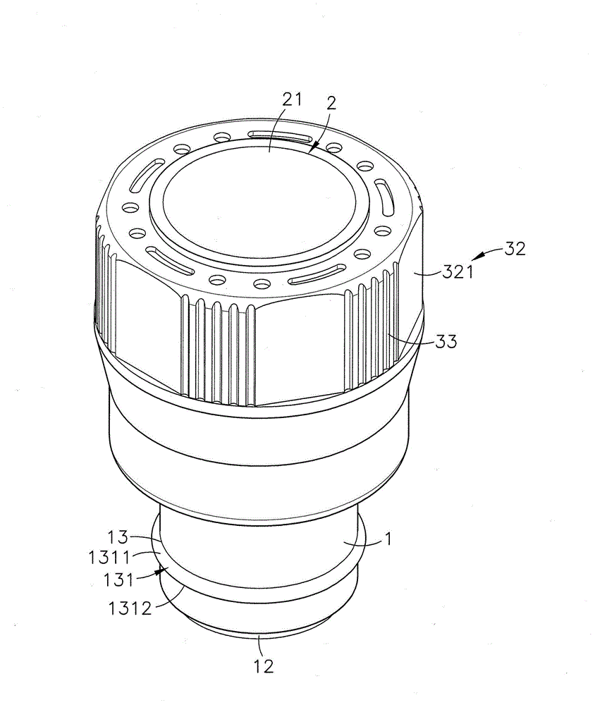
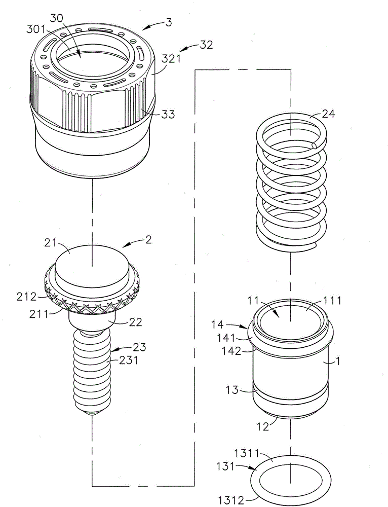
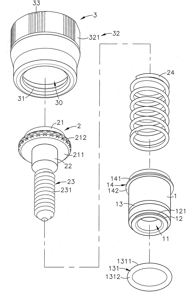
[0043] see figure 1 , figure 2 , image 3 , Figure 4 As shown, it is a three-dimensional appearance diagram, a three-dimensional exploded view, a three-dimensional exploded view of another viewing angle and a side sectional view of the present invention. It can be clearly seen from the figure that the present invention includes a sleeve 1, a fixing element 2 and an overcoat Tube 3, so the main components and features of this case are described in detail below, of which:

[0044] The sleeve 1 has a longitudinal hollow perforation 11 inside, and a concave accommodating groove 111 is provided above the perforation 11, and a ...


PUM


Abstract

The invention discloses a fixing device. In the fixing device, a positioning part is arranged below a perforated hole of a sleeve; an annular groove allowing a stop washer to be arranged in a sleeving manner is formed above the position adjacent to the positioning part; a rod body and a screw joint part extending from the head bottom surface of a fixing element penetrate through the perforated hole of the sleeve; an outer casing pipe is combined with the head part of the fixing element; an annular holding body is arranged below the accommodation space inside the outer casing pipe; the screw joint part for the fixing element is connected with the annular holding body of the outer casing pipe, and is then propped against the stop washer of the sleeve through the elastic deformation and resetting process, so as to form active sleeve joint; an actuation part and a pulling part are arranged outside the outer casing pipe; the actuation part can be driven by a hand tool, or the pulling part can be controlled manually; the outer sleeve can be screwed to drive the fixing element to be locked or unlocked between a first plate body and a second plate body, so that the plate-to-plate locking can be convenient.

Description

technical field [0001] The invention relates to a fixing device, especially a fixing device that can be easily rotated and locked or unlocked by hand tools or manual operation. A fixing element is inserted inside the sleeve, and an outer casing is assembled outside the head, and the outside of the outer casing is used to There is an actuating part and a wrenching part, which can be operated by hand tools or by bare hands, so as to facilitate the operation of the fixing device. Background technique [0002] When assembling general panels (board-to-board), lock them with positioning screws equipped with knobs, collars and screws, then fix the screws and collars on the first panel, and turn the knobs to make the screws In order to lock into the second panel to form a preset position, and then use hand tools to lock the screws, so that the first panel and the second panel are locked and fixed as one, and can be used in telecom bureau cabinets, industrial computers, and working m...

Claims


Application Information

Patent Timeline
IPC IPC(8): F16B5/02
CPCF16B5/02F16B5/0208
Inventor 曾英智
Owner HANWIT PRECISION IND LTD
Why Eureka
Try Eureka