Open-end spinning device

A technology of free-end and rotor, applied to open-end spinning machines, spinning machines, continuous winding spinning machines, etc., can solve the problems of complex structure design and high cost of free-end spinning devices, and achieve simple structure , Low manufacturing cost, low cost effect

Inactive Publication Date: 2015-04-29
SAURER GERMANY GMBH & CO KG
View PDF6 Cites 2 Cited by
  • Summary
  • Abstract
  • Description
  • Claims
  • Application Information

AI Technical Summary

Problems solved by technology

However, the structural design of the open-end spinning device is somewhat complex and expensive, especially due to the use of linear guide mechanisms

Method used


Image

  • Open-end spinning device
  • Open-end spinning device
  • Open-end spinning device

Examples


Embodiment Construction

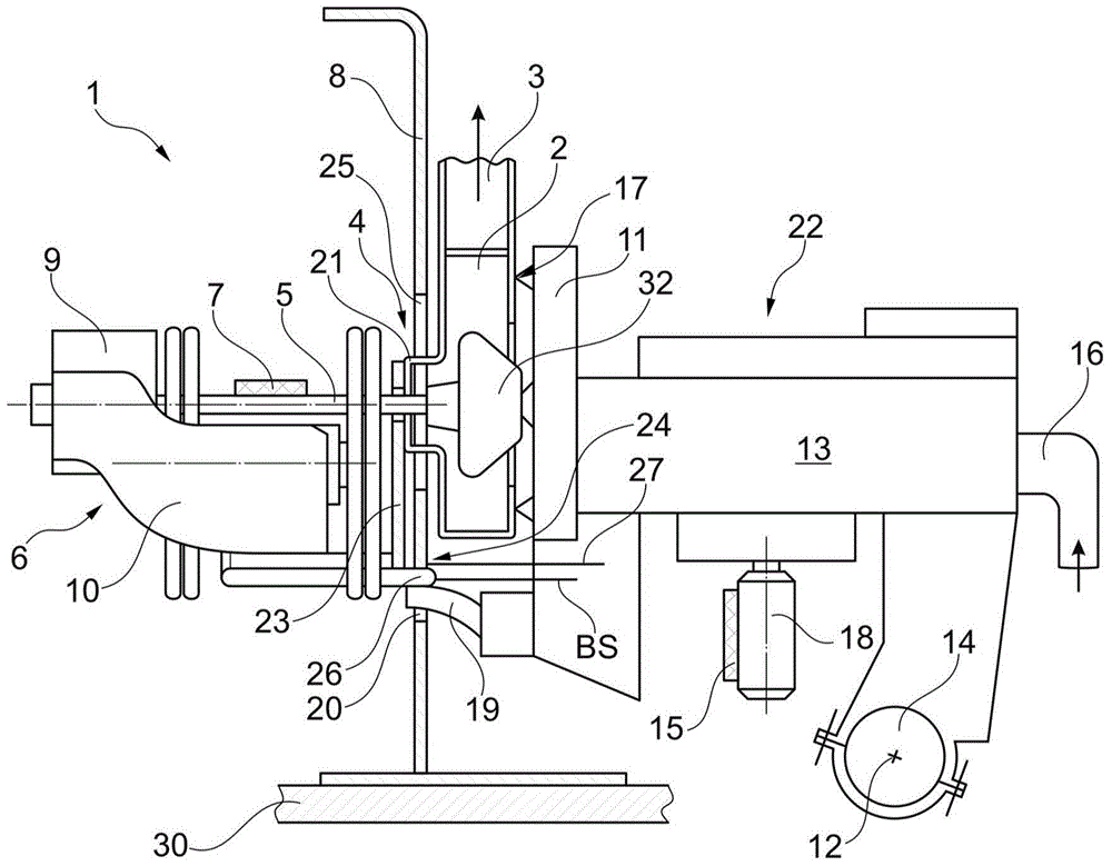
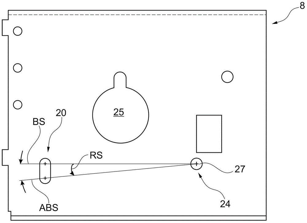
[0048] figure 1 The open-end spinning device 1 is schematically shown in its operating position BS, in which the rotor shaft bearing 10 is positioned such that the rotor shaft 5 of the spinning rotor 4 rests against the rotational edge from below. Machine length tangential drive belt7.

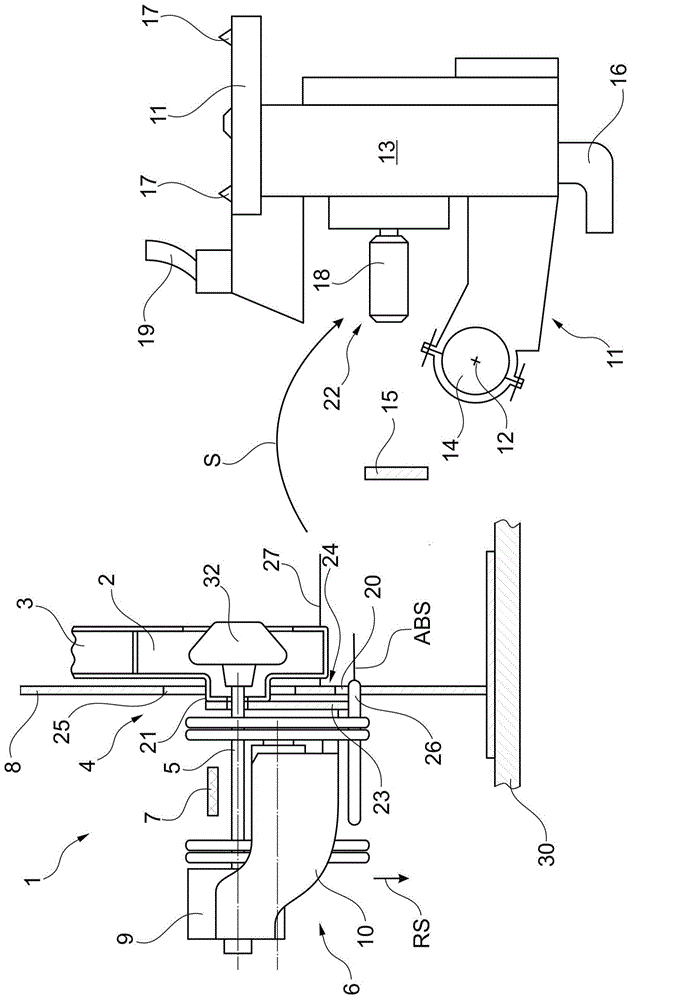
[0049] figure 2 The same open-end spinning device 1 is shown in the rest position ABS, that is to say in the position in which the rotor shaft bearing 10 is positioned such that the rotor of the spinning rotor 4 The cup shaft 5 is spaced from a revolving tangential drive belt 7 along the length of the machine.

[0050] As shown in the figure, the rotor housing 2 in which the rotor body 32 of the spinning rotor 4 rotates at high speed is closed by a cover 11 or by a sealing mechanism 17 and is passed through a flexible gas tube 3, for example a plastic hose Connected to a negative pressure source (not shown) for providing the negative pressure required for spinning.

[0051] In this exempl...


PUM


Abstract

The present invention relates to a spinning rotor of the open-end spinning device, the spinning rotor of the rotor shaft at the rotor shaft support mechanism, and the rotation along the length of the machine to cut the belt urging, spinning turn cup spinning rotor body can withstand operation in high-speed rotation of the rotor within a vacuum housing, rotor housing may be closed off by the cover member, sliver opening mechanism is integrated into the cover member, the rotor shaft support mechanism so installed and connected to the cover member via the connection means, i.e., the rotor shaft in the rotor housing is opened into a position, in the position out of contact with the rotor shaft of the rotary cutting machine along the length of the belt. Through the rotor shaft support means parallel to the rotor axis and laterally displaced with respect to the rotor shaft fixed to the fixed pivot support plate, and is equipped to guide positioning mechanism, the guide positioning mechanism has an upper position and a lower position in which the upper position , rotor shaft in a working position, in the lower position, the rotor axis positioning in the non-working position.

Description

technical field [0001] The invention relates to an open-end spinning device according to the first aspect of the invention. Background technique [0002] Such open-end spinning devices in relation to the stations of open-end rotor spinning machines have long been known and are explicitly described in various embodiments in the patent literature. [0003] Here, the known open-end spinning devices can be quite different, in particular with respect to a part of the structural design. [0004] An open-end spinning device is known, for example, from DE-OS 2130688, which has two separately arranged functional devices. Each functional device is now mounted individually on a central base frame of the open-end rotor spinning machine and is functionally connected to one another via fiber guide channels. [0005] The first functional device has a spinning part, namely a spinning rotor that rotates at a high rotational speed in a rotor housing that can withstand a negative pressure, t...

Claims


Application Information

Patent Timeline
Patent Type & Authority Applications(China)
IPC IPC(8): D01H4/12
CPCD01H4/12
Inventor H-G·瓦森霍芬
Owner SAURER GERMANY GMBH & CO KG
Why Eureka
Try Eureka