
Wind structure of automobile skylight

A technology for sunroofs and vehicles is applied in the field of windshield structures of vehicle sunroofs, which can solve the problems of increasing the overall cost, increasing the manufacturing cost, and being prone to failures, so as to reduce the frequency of failures, reduce the overall cost, and improve the height of the windshield. Effect

Inactive Publication Date: 2015-04-29
HSIN CHONG MACHINERY WORKS
View PDF5 Cites 6 Cited by
  • Summary
  • Abstract
  • Description
  • Claims
  • Application Information

AI Technical Summary

Problems solved by technology

[0002] Regarding the car sunroof, although it has the functions of air circulation and viewing above the car, the airflow around the car will flow into the car through the sunroof when the car is moving, and at the same time produce an uncomfortable wind cutting sound, so The advent of the windshield that covers the front of the sunroof
[0003] However, the known windshield used for the sunroof of a vehicle is an aluminum plate, and the windshield must be controlled to rise or fall electrically, for example, the windshield is controlled to rise when the sunroof is opened, or the windshield is raised when the sunroof is closed. The front control windshield is lowered. Therefore, the known windshield still has to rely on electricity to drive and cannot meet the current energy-saving design requirements. It also has a more complex structure and is more prone to failure due to the addition of an electric control mechanism. There may even be problems with maintenance difficulties and increased overall costs, which have long been a problem
[0004] In addition, the known windshield is a hard plate, which itself cannot overcome the problem of wind shearing, so other structures must be added to reduce the wind shearing, which will further increase the manufacturing cost.

Method used


Image

  • Wind structure of automobile skylight
  • Wind structure of automobile skylight
  • Wind structure of automobile skylight

Examples


Embodiment Construction

[0069] In order to further understand the characteristics, characteristics and technical content of the present invention, please refer to the following detailed description and drawings related to the present invention, but the attached drawings are only for reference and illustration, and are not intended to limit the present invention.

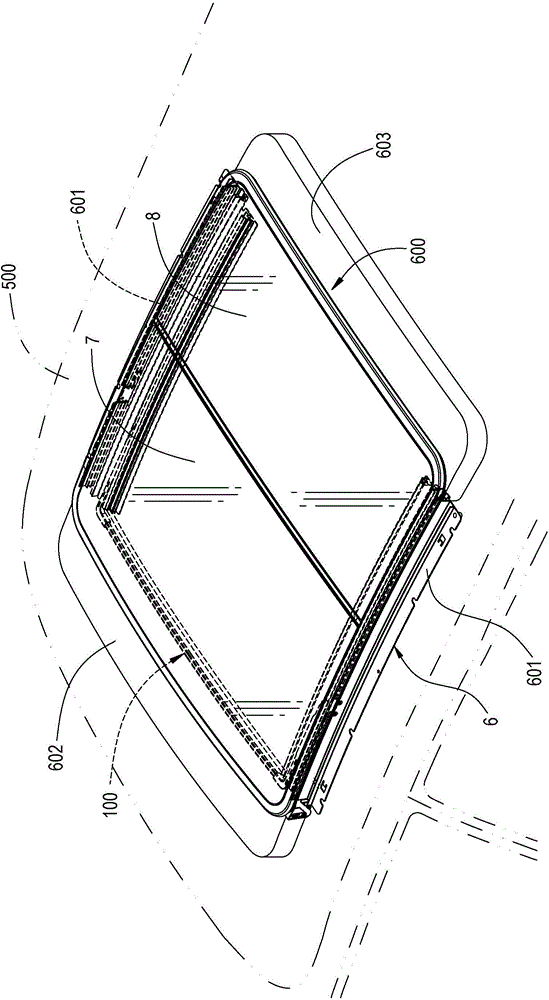
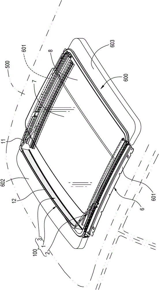
[0070] The invention provides a windshield structure for a sunroof for a vehicle, such as figure 2As shown, in order to be used in the vehicle sunroof 600, the vehicle sunroof 600 is mounted on the roof 500 of the vehicle, and the vehicle sunroof 600 includes a frame 6 (including two side frames 601, connected to the two side frames 601) provided on the roof 500. The front connecting block 602 between one end and the rear connecting block 603 connected between the other ends of the two side frames 601) and the moving mechanism (not marked) provided in the frame 6, a movable glass can be installed in the frame 6 to form A traditional single...


PUM


Abstract

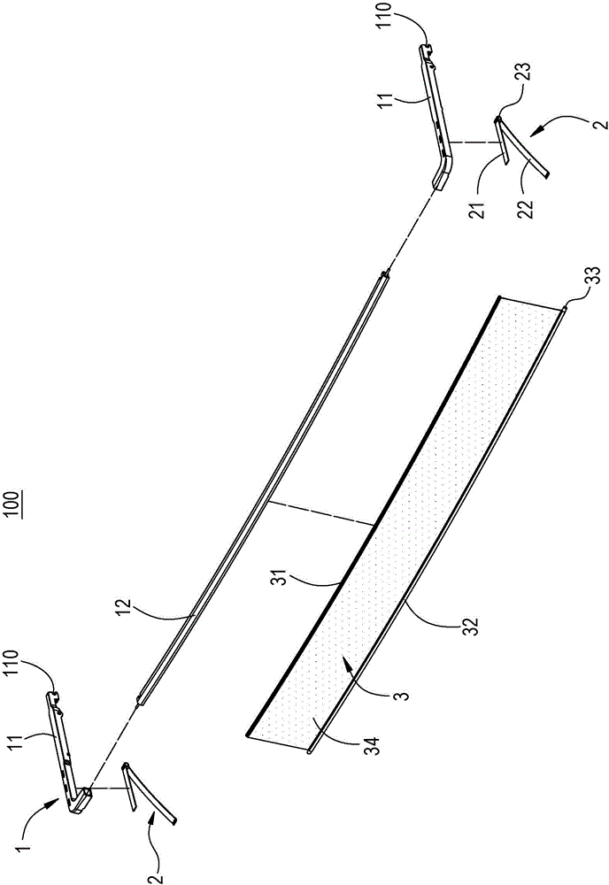
The invention discloses a wind structure of an automobile skylight. The automobile skylight comprises a framework and mobile glass arranged in the framework; the wind structure comprises a support frame, an elastic support piece and soft sheet, wherein the support frame is arranged in the framework in a pivoting manner movably and positioned under the mobile glass when the mobile glass is closed; the elastic support piece is arranged on the support frame and is supported between the support frame and the framework elastically; a plurality of through holes are distributed in the soft sheet; the upper and lower edges of the soft sheet are connected between the support frame and the framework. When the mobile glass is closed, the support frame is pressed downwards in a linkage manner, and the elastic support piece is pressed downwards accordingly; when the mobile glass is opened, force used for pressing the support frame downwards is removed in a linkage manner, the support frame is supported elastically by the elastic support piece, and the soft sheet is spread accordingly. Erecting and lying of the wind structure can be realized without being driven by power, the failure frequency is lowered, the structure is simplified, maintenance is easy, and the overall cost is reduced.

Description

technical field [0001] The invention relates to a windshield structure, in particular to a windshield structure for a vehicle sunroof. Background technique [0002] Regarding the car sunroof, although it has the functions of air circulation and viewing above the car, the airflow around the car will flow into the car through the sunroof when the car is moving, and at the same time produce an uncomfortable wind cutting sound, so There was the advent of the windshield in front of the sunroof. [0003] However, the known windshield used for the sunroof of a vehicle is an aluminum plate, and the windshield must be controlled to rise or fall electrically, for example, the windshield is controlled to rise when the sunroof is opened, or the windshield is raised when the sunroof is closed. The front control windshield is lowered. Therefore, the known windshield still has to rely on electricity to drive and cannot meet the current energy-saving design requirements. It also has a more...

Claims


Application Information

Patent Timeline
IPC IPC(8): B60J7/22
CPCB60J7/22
Inventor 黄耀德苏德宗江贵交
Owner HSIN CHONG MACHINERY WORKS
Learn More