Angle iron punching machine added with chamfering function

A punching machine and chamfering technology, applied in the direction of perforating tools, forming tools, manufacturing tools, etc., can solve the problems of easy hand injury, low efficiency, high risk, etc., to facilitate chamfering processing, ensure stability, and overall good performance

Inactive Publication Date: 2015-04-29
CHONGQING XINZHUOHUI AUTOMOBILE PURIFIER
View PDF0 Cites 1 Cited by
  • Summary
  • Abstract
  • Description
  • Claims
  • Application Information

AI Technical Summary

Problems solved by technology

There are two ways of chamfering, which are manual chamfering and mechanical chamfering. Manual chamfering is processed manually with a file or using a grinding wheel to chamfer or process one by one. The chamfering quality is uneven, the chamfering speed is slow, and the efficiency is low; the mechanical chamfering is to use a chamfering machine to chamfer the workpiece, which has high efficiency, but is expensive, takes up a lot of space and has many disadvantages
Existing angle iron punching machines only have the function of punching, but no chamfering function. After the punching is completed, the punched workpiece can only be taken out and placed on the chamfering machine for chamfering or manual chamfering, and the workpiece The handling link will lead to the prolongation of the entire chamfering processing time, the reduction of efficiency, and the increase of manual handling costs

Method used


Image

  • Angle iron punching machine added with chamfering function
  • Angle iron punching machine added with chamfering function

Examples


Embodiment Construction

[0011] Below in conjunction with accompanying drawing and specific embodiment the present invention will be described in further detail:

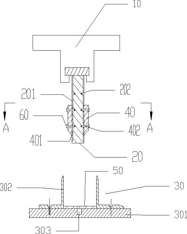
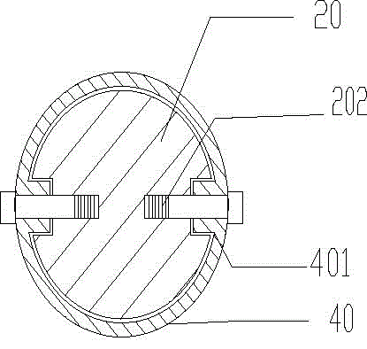
[0012] Such as figure 1 with figure 2 As shown, the angle iron punching machine attached to the angle of this embodiment includes a punching power device 10, a punching head 20, and a base 30. The base 30 is located below the punching head 20, and the punching power device 10 is located at the punching Above the head 20, the punching power unit 10 drives the punching head 20 to move in a direction perpendicular to the base 30. The outer wall of the punching head 20 is provided with a chamfering head 40, and the inner wall of the chamfering head 40 and the outer wall of the punching head 20 The center axes of the chamfering head 40 and the punching head 20 coincide; the base 30 includes a base plate 301 and a positioning slider 302, the base plate 301 is provided with a die 303, the processed object 50 is placed on the base plate 301, and ...


PUM


Abstract

The invention relates to an angle iron punching machine, in particular to an angle iron punching machine added with a chamfering function. The angle iron punching machine comprises a punching power device, a punching head and a base, wherein the base is located below the punching head; the punching head is located below the punching power device; the punching power device drives the movement direction of the punching head to be vertical to the base; the angle iron punching machine is characterized in that the outer wall of the punching head is sleeved by a chambering head; the inner wall of the chambering head is in attached contact with the outer wall of the punching head; the center lines of the chambering head and the punching head are located on the same axis. The invention provides a chamfering machine capable of simultaneously punching and chambering to overcome the problem that an existing angle iron punching machine does not have the chambering function, so that the processing efficiency is improved; the processing cost is reduced; the occupied space is reduced.

Description

technical field [0001] The invention relates to an angle iron punching machine, in particular to an angle iron punching machine with chamfers. Background technique [0002] The angle iron punching machine is specially used for punching holes in metal plates such as angle iron, flat iron, copper and aluminum row. After the drilling is completed, the hole wall and the board surface are at a 90-degree right angle to prevent the sharp edges from causing injury to the staff. For safety reasons, it must be chamfered. On the one hand, the role of chamfering is to remove the burrs and sharp edges caused by machining on the parts, which can not only ensure safety and beautiful structure, but also to facilitate the installation of parts by the staff, such as the installation of bearings. In addition, there are some arc chamfers (or arc transitions) that can also reduce stress concentration and strengthen the strength of shaft parts. Therefore, on mechanical parts, especially round fi...

Claims


Application Information

Patent Timeline
Patent Type & Authority Applications(China)
IPC IPC(8): B21D35/00B21D37/10B21D28/14B21D28/34
Inventor 杨云逸
Owner CHONGQING XINZHUOHUI AUTOMOBILE PURIFIER
Why Eureka
Try Eureka