
A microfluidic chip and method for preparing nanocapsules using it

A microfluidic chip and channel technology, which is applied in the field of microfluidic chip preparation, can solve problems such as the inability to meet the preparation requirements of hollow nanoparticles, and achieve the effects of intact particles, uniform shape, and high integration

Active Publication Date: 2017-01-18
THE NAT CENT FOR NANOSCI & TECH NCNST OF CHINA
View PDF1 Cites 1 Cited by
  • Summary
  • Abstract
  • Description
  • Claims
  • Application Information

AI Technical Summary

Problems solved by technology

However, the disclosed microfluidic chip only has a two-stage structure, and the synthesized nanoparticles have a solid structure, which cannot meet the preparation requirements of the prior art for hollow nanoparticles.

Method used


Image

  • A microfluidic chip and method for preparing nanocapsules using it
  • A microfluidic chip and method for preparing nanocapsules using it
  • A microfluidic chip and method for preparing nanocapsules using it

Examples


Embodiment 1

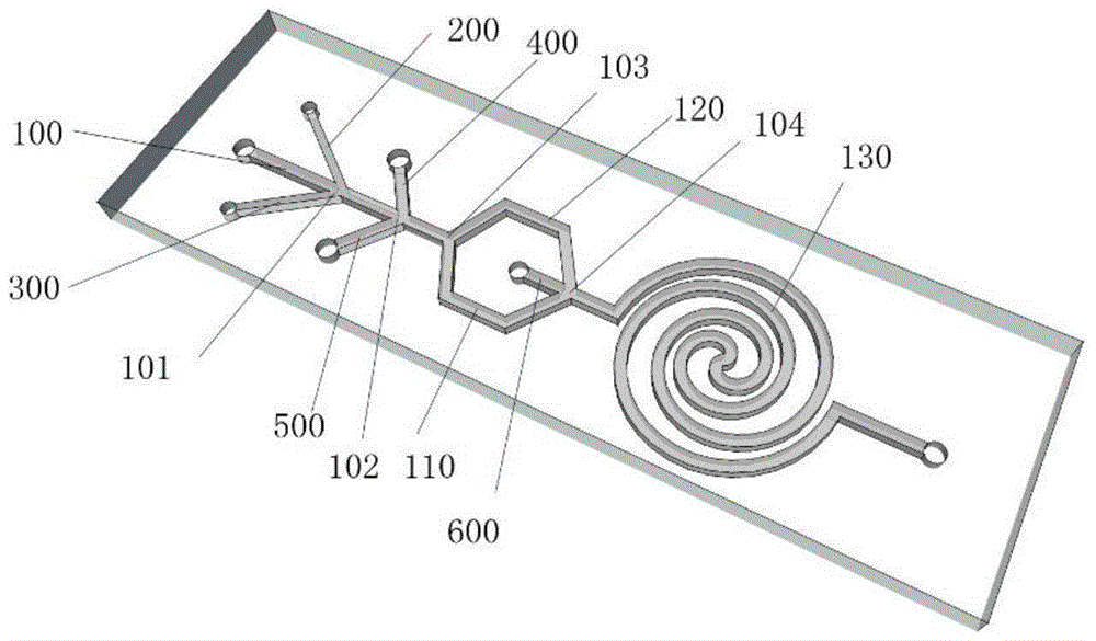
[0067] A microfluidic chip, such as figure 1 ( figure 1 As shown in the structural schematic diagram of the microfluidic chip provided in Example 1), it includes: a first channel 100, a second channel 200, a third channel 300, a fourth channel 400, a fifth channel 500, a sixth channel 600 and a Eight passages 130; the eighth passage 130 is a double helix structure; the first passage 100, the second passage 200, the third passage 300, the fourth passage 400, the fifth passage 500, and the sixth passage 600 all have an independent inlet, the eighth channel 130 has a unique independent outlet;

[0068] Among them, the second channel 200 and the third channel 300 are distributed on both sides of the first channel 100, and intersect with the first channel 100 at the first node 101; the fourth channel 400 and the fifth channel 500 are distributed on both sides of the first channel 100 side, and intersects with the first passage 100 and passes through the second node 102;

[0069]...

Embodiment 2

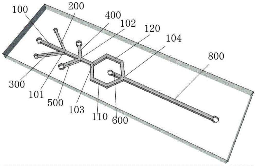
[0083] A microfluidic chip, such as figure 2 ( figure 2 As shown in the structural schematic diagram of the microfluidic chip provided in Example 2), the difference from the microfluidic chip provided in Example 1 is that the eighth channel 130 is a linear structure.

Embodiment 3

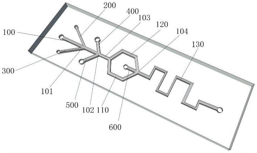
[0085] A microfluidic chip, such as image 3 ( image 3 As shown in the structural schematic diagram of the microfluidic chip provided in Example 3), the only difference from the microfluidic chip provided in Example 1 is that the eighth channel 130 has a rectangular wave structure.


PUM


Abstract

The invention relates to a micro-fluidic chip which comprises a first passage, a second passage, a third passage, a fourth passage, a fifth passage and a sixth passage e, wherein a first node, a second node and a third node are sequentially distributed on the first passage along forward flow, and the first passage is divided into a first sub passage and a second sub passage after the third node; the first sub passage and the second sub passage intersect at a fourth node to interflow to be an eighth passage; the second passage and the third passage are distributed on the two sides of the first passage, and are communicated with the first passage through the first node; the fourth passage and the fifth passage are distributed on the two sides of the first passage, and are communicated with the first passage through the second node; the sixth passage is communicated, at the fourth node, with the first sub passage, the second sub passage and the eighth passage. The micro-fluidic chip provided by the invention has a multistage structure, can be used for preparing hollow nano-particles with multistage core-shell structures, and achieves the possibility of packaging and loading different medicines.

Description

technical field [0001] The invention belongs to the field of microfluidic chip preparation, and relates to a microfluidic chip and a method for preparing nanocapsules by using the microfluidic chip. The microfluidic chip has a multi-level structure and can controllably synthesize general-purpose functional nanocapsules with stable structures. For the construction of nano-transportation system. Background technique [0002] Currently, nano-transport systems are developing rapidly. Nanoparticles are used as carriers to deliver drugs to specific cells or carry imaging agents to assist in imaging, which has greatly improved the efficacy of diseases, reduced the toxicity of drugs and adjuvants, and realized the concept of integrated diagnosis and treatment. Nanotechnology is widely used in disease diagnosis, treatment, prognosis and other aspects. [0003] At present, the entrapped delivery of drugs or other molecules usually requires the design of different carriers for drug m...

Claims


Application Information

Patent Timeline
Patent Type & Authority Patents(China)
IPC IPC(8): B01L3/00A61K9/51B82Y5/00
Inventor 蒋兴宇冯强张璐孙佳姝
Owner THE NAT CENT FOR NANOSCI & TECH NCNST OF CHINA
Learn More