A kind of multifunctional health care chair
A multifunctional, health-care chair technology, applied in sports accessories, training equipment for adjusting cardiovascular system, training equipment for adjusting coordination, etc., can solve problems such as side effects and doubtful sequelae
- Summary
- Abstract
- Description
- Claims
- Application Information
AI Technical Summary
Problems solved by technology
Method used
Image
Examples
Embodiment 1
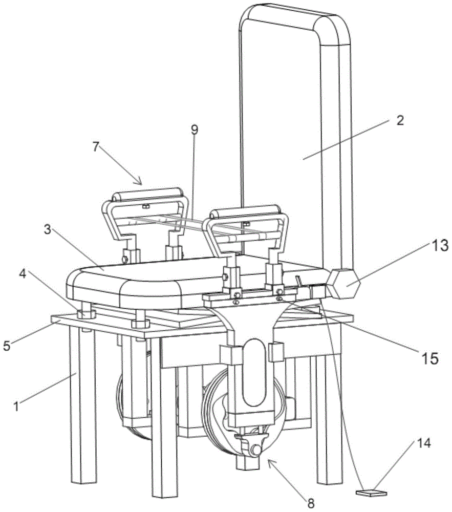
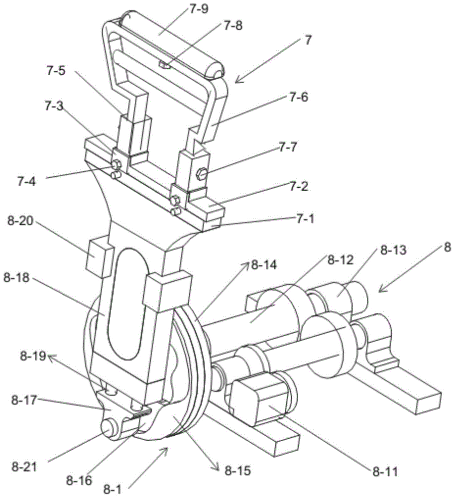
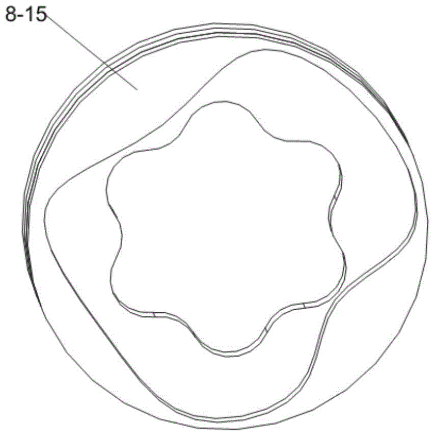
[0042] Example 1, see Figure 1 to Figure 4 , a multifunctional health care chair, comprising a chair frame 1, a backrest 2, a chair surface 3 and a symmetrically arranged armrest assembly 7, the top of the chair frame 1 is provided with a support table 5, and the top of the support table 5 is provided with Adjustable support frame 6, the purpose of this adjustable support frame is to adjust the height of the chair surface from the ground, especially when having sex in a standing position, it is particularly important. Its structure can adopt the existing lifting tower structure, and it will not be repeated here. There is only support and no connection between the upper end of the adjustment support frame and the seat surface. The seat surface 3 is placed above the support frame 6, and the rear end of the seat surface 3 is hinged with the backrest 2 through the hinge assembly 13. When in use The angle between the backrest and the seat surface can be adjusted by adjusting the h...
Embodiment 2
[0047] Example 2, see Figure 5 , the drive mechanism adopts a cam mechanism 8-2, mainly including a drive motor 8-20, the drive motor is hoisted on the chair frame 1, and the output end of the drive motor 8-20 is connected to the main shaft 8-21 through a transmission member , the main shaft is installed on the chair frame 1 through the support assembly 8-22, the two ends of the main shaft 8-21 are connected with a cam 8-23, and the corresponding cam position is provided with a push rod 8-24, and the push rod 8 -24 is installed between two parallel slide rails 8-25, the slide rails are fixedly installed on the chair frame 1, and the upper end of the push rod is connected to the armrest assembly 7. The push rod can also be omitted in the upper structure, and the armrest assembly is directly in contact with the cam. All the other structures are the same as in Example 1.
Embodiment 3
[0048] Example 3, see Image 6 , the drive mechanism adopts a link mechanism 8-3, mainly including a drive motor 8-30, the drive motor is hoisted on the chair frame 1, and the output end of the drive motor is connected to the main shaft 8-31 through a transmission member, so The main shaft is installed on the chair frame 1 through a support assembly 8-32, and the two ends of the main shaft are connected with an eccentric wheel 8-33, and a connecting rod 8-34 is hingedly mounted on the eccentric wheel 8-33, and the connecting rod The other end of the armrest assembly 7 is hingedly connected. All the other structures are the same as in Example 1.
PUM
 Abstract
Description
Claims
Application Information
 - Generate Ideas
- Intellectual Property
- Life Sciences
- Materials
- Tech Scout
- Unparalleled Data Quality
- Higher Quality Content
- 60% Fewer Hallucinations
Browse by: Latest US Patents, China's latest patents, Technical Efficacy Thesaurus, Application Domain, Technology Topic, Popular Technical Reports.
© 2025 PatSnap. All rights reserved.Legal|Privacy policy|Modern Slavery Act Transparency Statement|Sitemap|About US| Contact US: help@patsnap.com


