
Magnetic heat power generation device

A technology of magnetothermal power generation and hard magnetism, which is applied in the direction of thermoelectric devices, generators/motors, and electrical components that utilize thermal changes in magnetic permeability, can solve problems such as unreasonable structures, and achieve improved adjustability and improved assembly Efficiency and structural stability, the effect of changing the accuracy of the dwelling station

Active Publication Date: 2015-04-22
FOSHAN CHENG XIAN TECH CO LTD
View PDF4 Cites 2 Cited by
  • Summary
  • Abstract
  • Description
  • Claims
  • Application Information

AI Technical Summary

Problems solved by technology

[0005] The purpose of the present invention is to provide a magnetothermal power generation device, which aims to solve the problem of unreasonable structure in the prior art, so that the accuracy of the rotor’s dwelling position can be adjusted, the heating and cooling rate of the stator’s soft magnetic field is higher, and the thermal energy conversion rate is higher. High, simplifies the overall structure, reduces the difficulty of the rotor mold opening process, and improves the structural stability

Method used


Image

  • Magnetic heat power generation device
  • Magnetic heat power generation device
  • Magnetic heat power generation device

Examples


Embodiment Construction

[0030] The present invention will be described in further detail below in conjunction with the accompanying drawings, but the embodiments of the present invention are not limited thereto.

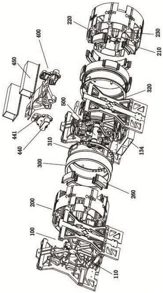
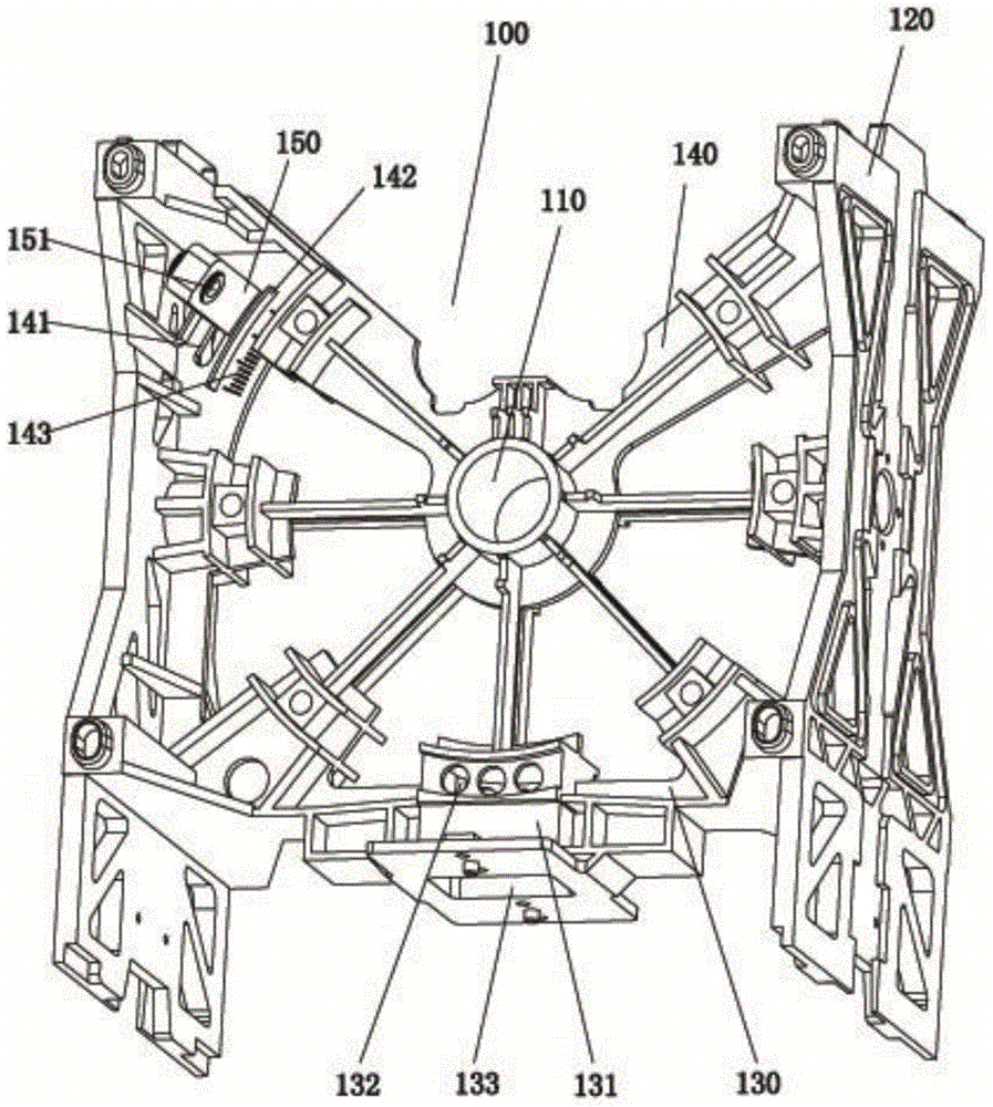
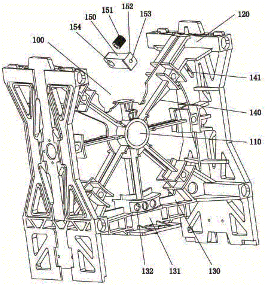
[0031] Such as figure 1 As shown, a magneto-caloric power generation device according to the present invention includes at least one magneto-caloric power generation unit, and the magneto-caloric power generation unit includes two main supports 100, a rotor 200, a stator 300 and a heating and cooling device 400 that are connected and arranged correspondingly. , the main support 100 is provided with a shaft seat A110, and the rotor 200 is provided with a shaft seat B210, an accommodation space is formed between the two main supports 100, the rotor 200 is located in the accommodation space, and the power shaft 500 passes through two The axle seat A110 and the axle seat B210 are arranged so that the rotor 200 is rotatably arranged in the accommodation space, the two stators 300 are fixedly arr...


PUM


Abstract

The invention relates to the technical field of magnetic heaters, in particular to a magnetic heat power generation device. The magnetic heat power generation device comprises two main supports, a rotor, a stator and a heating and cooling device, wherein the two main supports are correspondingly connected. The rotor comprises an annular support, the two sides of the annular support are each provided hard magnetic fixing grooves at even group numbers, and a plurality of magnet locking plates which are in one-to-one correspondence to the hard magnetic fixing grooves are arranged on the annular support. The connection portions of one supporting beam and the main supports are provided with adjusting grooves, mounting brackets are arranged on the adjusting grooves and are provided with lingering static magnets, and the two sides of the connection portion of a mounting plate and a transferring arm are each provided with a heat insulation plate. By the adoption of the structure, the accuracy of lingering working stations of the rotor and the stator can be effectively changed, the adjustability of a grouped assembly structure is improved, a pipeline for heating cooling fluid is larger, the cold and hot conversion rate of soft magnetism is accelerated, the utilization efficiency and the conversion efficiency of heat energy are improved, the structure of the rotor is simplified, the difficulty for die sinking is reduced, and the assembling efficiency and the structural stability are improved.

Description

technical field [0001] The invention relates to the technical field of magnetocaloric engines, in particular to a magnetocaloric power generation device. Background technique [0002] The magnetothermal power generation device is a thermal energy utilization device that converts thermal energy into magnetic energy, and then converts the magnetic energy into mechanical energy to generate power. It generally includes a stator equipped with soft magnets, a rotor equipped with hard magnets, and soft magnetic heating and heating in the stator. Cooling heating cooling system. [0003] Existing magnetocaloric power generation devices have unreasonable structural settings, which are specifically manifested in the following aspects: 1. In the heating and cooling system, the heating device and the cooling device respectively heat and cool the soft magnets, the structure is large in volume, the pipeline is complicated, and the integrated The temperature is low, and the heating and coo...

Claims


Application Information

Patent Timeline
Patent Type & Authority Applications(China)
IPC IPC(8): H02N11/00H10N15/20
CPCH02N11/002H10N15/20
Inventor 赵天安刘利龙克文
Owner FOSHAN CHENG XIAN TECH CO LTD
Learn More