
Method for adjusting the critical speed of high-speed combined rotor of micro turbojet engine

A turbojet engine and critical speed technology, which is applied in the direction of engine testing, electric speed/acceleration control, machine/structural component testing, etc., can solve the problem of increasing the space and weight of the aircraft, and not calculating the sensitivity of the combined rotor critical speed , reduce reliability and other issues, to avoid numerical instability, reduce blindness, and save time

Active Publication Date: 2015-04-22
SICHUAN AEROSPACE ZHONGTIAN POWER EQUIP CO LTD
View PDF3 Cites 8 Cited by
  • Summary
  • Abstract
  • Description
  • Claims
  • Application Information

AI Technical Summary

Problems solved by technology

[0005] The traditional method does not calculate the sensitivity of each influencing factor to the critical speed of the combined rotor, but only adjusts the structural dimensions of some parts of the engine according to relevant theories, so as to achieve the purpose of adjusting the critical speed, which has a certain degree of blindness
[0006] The traditional method mostly uses the transfer matrix to calculate the critical speed of the joint rotor. The traditional method is mostly applied to low-speed and large-scale rotors. The method of adding a critical speed adjustment device outside the rotor is used to adjust the critical speed, thereby increasing the space and weight of the aircraft. , which reduces the reliability

Method used


Image

  • Method for adjusting the critical speed of high-speed combined rotor of micro turbojet engine
  • Method for adjusting the critical speed of high-speed combined rotor of micro turbojet engine
  • Method for adjusting the critical speed of high-speed combined rotor of micro turbojet engine

Examples


Embodiment Construction

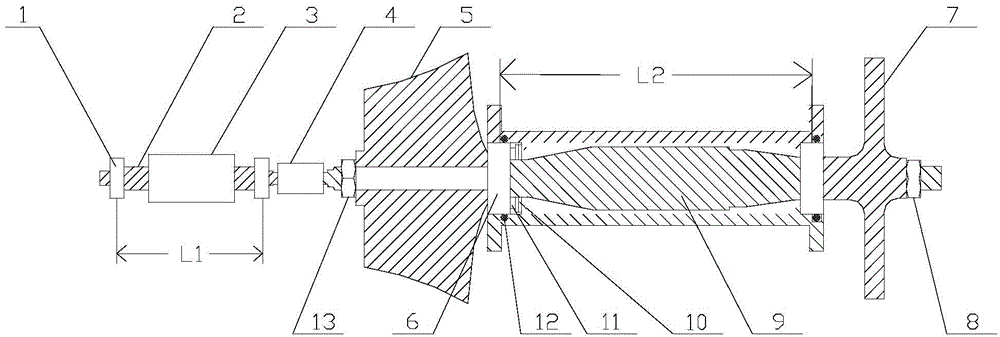
[0031] Such as figure 1 As shown, select a micro-turbojet engine for use in the present embodiment, the rated speed is 106000r / min, and the working speed is 85000r / min-100000r / min.

[0032] a. Based on the finite element calculation model, test the critical speed of the combined rotor within the working speed, and define it as the theoretical calculation value of the critical speed A, and define the measured value of the critical speed test of the combined rotor as B; by △=|(A-B) / B|×100% to get the error value △, judge whether the range of the error value △ is 0-5%, if it is, there is no need to adjust the finite element calculation model, if not, it is necessary to correct the finite element calculation model, and finally make the error The value Δ is within 0-5%.

[0033] The calculation results are shown in Table 1:

[0034]

[0035] Table 1

[0036] The difference between the theoretical calculation value A of the critical speed of the rotor critical speed and the m...


PUM


Abstract

The invention provides a method for adjusting the critical speed of a high-speed combined rotor of a micro turbojet engine. By adopting the method, no special critical speed adjusting device needs to be mounted outside an engine shafting. Thus, the aircraft space is saved, the weight is reduced, and the reliability is improved. The critical speed of a high-speed combined rotor is adjusted by changing the structure size of engine parts. The method is simple and feasible.

Description

technical field [0001] The invention relates to a method for adjusting the critical rotational speed of a rotor system, in particular to a method for adjusting the critical rotational speed of a high-speed joint rotor of a micro turbojet engine. Background technique [0002] Many machines in aviation, petrochemical, electric power, shipbuilding and even general factories have rotating parts - rotors. For example, aero turbine engines, steam turbines, gas turbines, gas compressors, and blowers are rotor-based machines, all of which are collectively referred to as rotating machines. Rotating machinery often has such a phenomenon: Although the rotor is statically and dynamically balanced, when the rotor speeds up (or slows down) to a certain speed, the rotor system resonates and the machine vibrates violently. The speed at this time is called the critical speed. . It is dangerous for the machine to run at the critical speed, and the critical speed must be adjusted to keep it ...

Claims


Application Information

Patent Timeline
Patent Type & Authority Applications(China)
IPC IPC(8): G05D13/62G01M15/00G06F17/50
Inventor 刘颖李子华丁红华
Owner SICHUAN AEROSPACE ZHONGTIAN POWER EQUIP CO LTD
Learn More