a dehydration device

A technology of dehydration device and dehydration cylinder, which is applied in the direction of washing device, textile and papermaking, household appliances, etc., which can solve the problems of poor dehydration effect of the device, achieve the effect of improving dehydration effect, facilitating cooling work, and prolonging the service life

Inactive Publication Date: 2016-07-06
张秀岭
View PDF5 Cites 0 Cited by
  • Summary
  • Abstract
  • Description
  • Claims
  • Application Information

AI Technical Summary

Problems solved by technology

At present, although there are many dehydration devices on the market, the dehydration effect of these devices is not very good.

Method used


Image

  • a dehydration device
  • a dehydration device

Examples


Embodiment Construction

[0019] Below, in conjunction with accompanying drawing and specific embodiment, the present invention is described further:

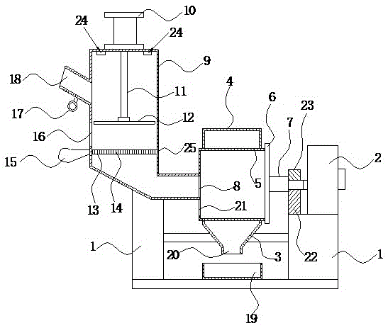
[0020] like figure 1 As shown, it is a dehydration device of the present invention, comprising a bracket 1, a motor 2 mounted on the bracket 1, a fixed shell, a dehydration cylinder 5 horizontally and rotatably installed in the fixed shell, and the peripheral wall of the dehydration cylinder 5 There are a plurality of first dehydration holes (not shown in the figure), and the right end of the dehydration cylinder 5 is detachably connected with an end cover 6, and the end cover 6 is fixedly connected with a rotating shaft 7, and the rotating shaft 7 is connected to the The output shaft of the motor 2 is connected, the left end side wall of the dehydration cylinder 5 is provided with a through hole 8, and the water squeeze shell 9 is also installed on the support 1, and the water squeeze shell 9 is connected to the dehydration cylinder through the through...


PUM


Abstract

The invention discloses a dehydrating device which comprises a bracket, a motor, a fixed housing and a dehydrating barrel, wherein a plurality of first dehydrating holes are formed in the peripheral wall of the dehydrating barrel; the right end of the dehydrating barrel is connected with an end cover; a rotary shaft is fixedly connected on the end cover; the rotary shaft is connected with an output shaft of the motor; the left end of the dehydrating barrel is communicated with a water extruding barrel; a first discharge door which can be opened and closed is further arranged on the left end side wall of the dehydrating barrel; a water outlet is formed in the bottom of the fixed housing; the side wall of the water extruding shell is connected with a feeding tube; a gas cylinder is fixedly arranged on the top of the water extruding shell; a pushing block is arranged in the water extruding shell; the pushing block is connected with a piston rod of the gas cylinder; a dehydrating plate is transversely inserted in the water extruding shell; the dehydrating plate is positioned below the feeding tube; a plurality of second dehydrating holes are formed in the dehydrating plate; a positioning slot for allowing the front end of the dehydrating plate to insert is formed in the inner side wall of the water extruding shell. The dehydrating device can be integrated with an extruding dehydrating function and a rotary centrifugal dehydrating function, so that the dehydrating effect is remarkably improved.

Description

technical field [0001] The invention relates to a dehydration device. Background technique [0002] In real life, it is often necessary to dehydrate and dry some such as clothing, shoes, carpets, and quilt covers after cleaning. At present, although there are many dehydration devices on the market, the dehydration effect of these devices is not very good. Contents of the invention [0003] In view of the deficiencies in the prior art, the purpose of the present invention is to provide a dehydration device which can integrate the functions of extrusion dehydration and rotary centrifugal dehydration, and significantly improve the dehydration effect. [0004] To achieve the above object, the present invention adopts the following technical solutions: [0005] A dehydration device, comprising a bracket, a motor mounted on the bracket, a fixed shell, and a dehydration cylinder horizontally and rotatably installed in the fixed shell, the peripheral wall of the dehydration cyli...

Claims


Application Information

Patent Timeline
Patent Type & Authority Patents(China)
IPC IPC(8): D06F49/00D06F47/04
CPCD06F47/04D06F49/00
Inventor 练志伟
Owner 张秀岭
Why Eureka
Try Eureka