An automatic nail-piercing device compatible with 1-4 pole circuit breakers
What is Al technical title?
Al technical title is built by PatSnap Al team. It summarizes the technical point description of the patent document.
A circuit breaker and automatic threading technology, which is applied in the field of automatic assembly, can solve problems such as unqualified product quality, increased production costs, and low production efficiency, and achieve the effects of improving speed and efficiency, increasing working speed, and improving production efficiency
Inactive Publication Date: 2016-06-08
浙江汇聚自动化设备有限公司
View PDF7 Cites 0 Cited by
Summary
Abstract
Description
Claims
Application Information
AI Technical Summary
This helps you quickly interpret patents by identifying the three key elements:
Problems solved by technology
Method used
Benefits of technology
Problems solved by technology
The traditional method is usually to manually insert the rivet into the riveting hole. This method has low production efficiency and is prone to missing rivets, resulting in unqualified product quality.
[0003] At present, there are a small number of automatic nailing devices on the market, but these automatic nailing devices use a fixed stroke method, and can only be used for automatic nailing for specific types of circuit breakers, such as 1-pole circuit breakers and 2-pole circuit breakers. , 3-pole circuit breaker and 4-pole circuit breaker respectively need 4 different types of automatic nailing devices for automatic nailing, which virtually increases the production cost
Method used
Image
Click on the blue label to locate the original text in one second.
Reading with bidirectional positioning of images and text.
Examples
Embodiment Construction
[0033] The present invention will be further described in detail below with reference to the drawings and specific embodiments.
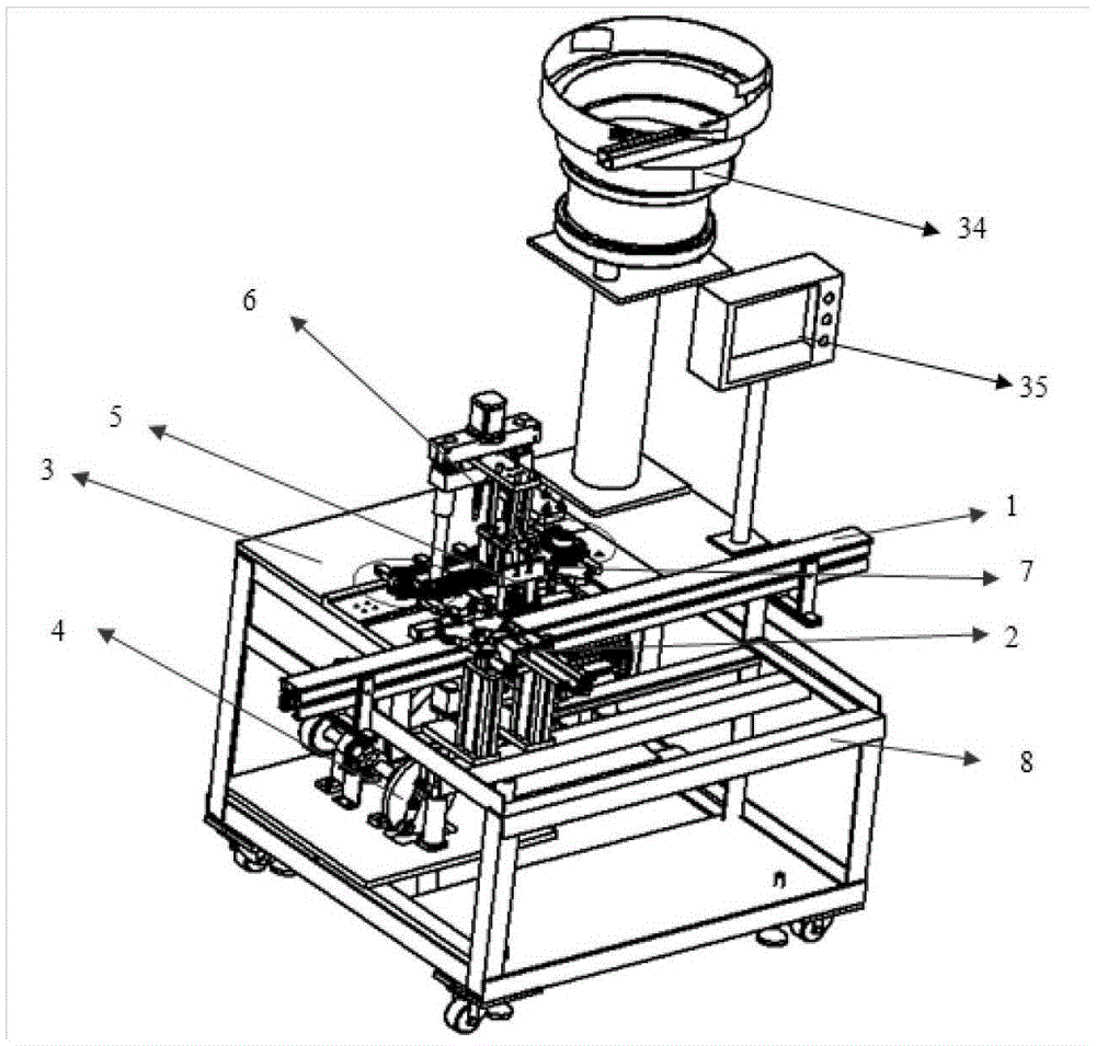
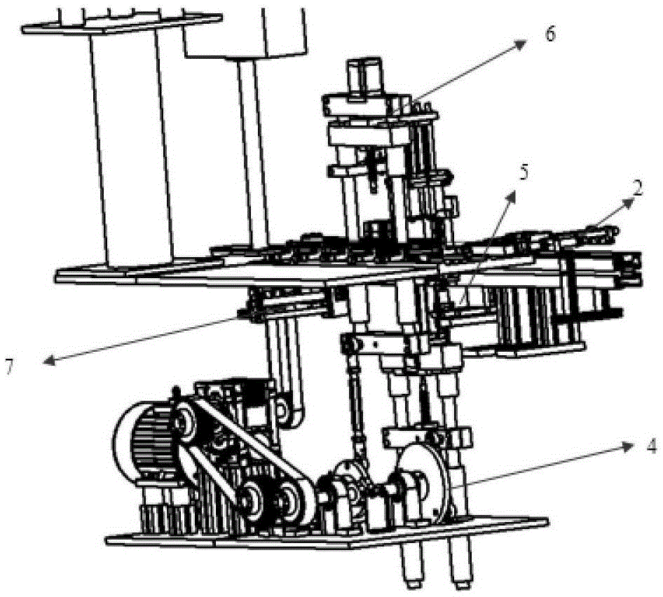
[0034] Such as Figure 1-8 As shown, the present invention provides an automatic nail-piercing device compatible with a 1-4 pole circuit breaker, which includes a conveyor belt 1, a feeding mechanism 2, a table top mechanism 3, a nail-piercing guide mechanism 4, a nail falling mechanism 5, and a nail pressing mechanism 6. Unloading mechanism 7 and frame 8;
[0035] The conveyor belt 1 is used to convey the workpieces to be nailed. The conveyor belt 1 adopts the form of a chain plate assembly line, which is compatible with the production lines of most production enterprises. The front is a manual assembly workbench, and the rear flows to the automatic riveting equipment; the feeding mechanism 2 Set on the side of the conveyor belt 1;
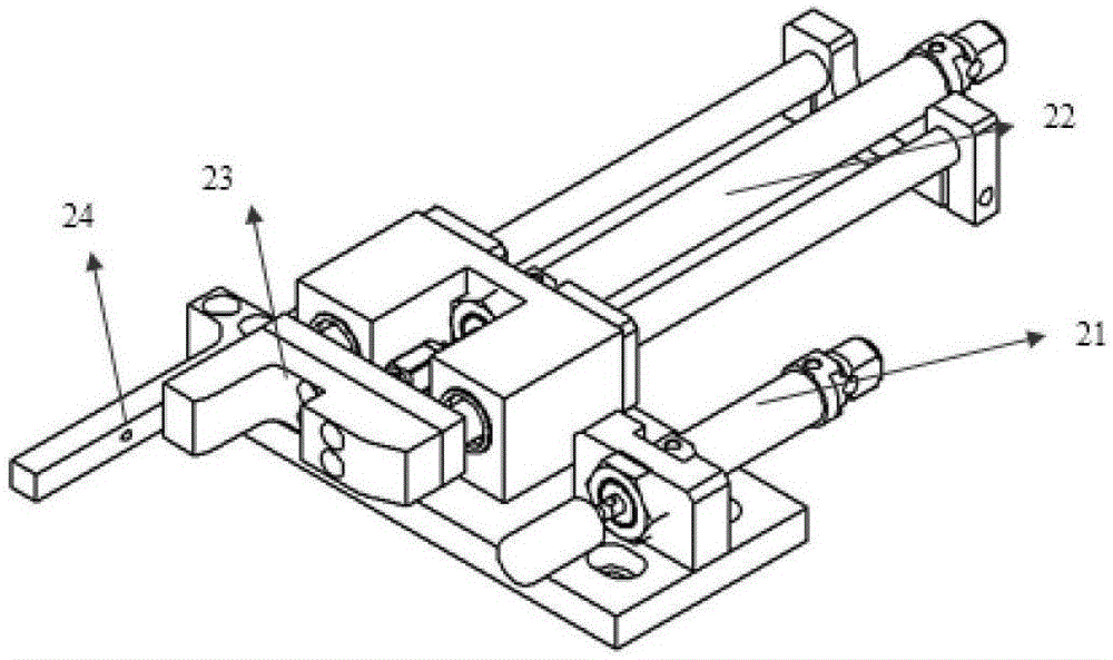
[0036] The feeding mechanism 2 includes a feeding spacer cylinder 21, a feeding feeding cylinder 22, a feeder 23, and an ...
PUM
Abstract
The invention provides an automatic rivet penetrating device compatible with a 1-pole circuit breaker, a 2-pole circuit breaker, a 3-pole circuit breaker and a 4-pole circuit breaker. The automatic rivet penetrating device comprises a conveyor belt, a feeding mechanism, a working tabletop mechanism, a rivet penetrating guide mechanism, a rivet falling mechanism, a rivet pressing mechanism, a discharging mechanism and a rack. The conveyor belt is used for conveying a workpiece into which a rivet is about to penetrate. The feeding mechanism is arranged on the side face of the conveyor belt. The rivet penetrating guide mechanism, the rivet falling mechanism and the rivet pressing mechanism cooperatively work and conduct automatic rivet penetration, and automatic discharge is conducted through the discharging mechanism. The rivet penetrating guide mechanism, the rivet falling mechanism and the rivet pressing mechanism are each provided with a type changing motor assembly, the type changing motor assemblies can adapt to rivets of different lengths through lead screws and motors, and then the automatic rivet penetrating device is universal for the 1-pole circuit breaker, the 2-pole circuit breaker, the 3-pole circuit breaker and the 4-pole circuit breaker. In the type changing process, the type changing motor assemblies can automatically adjust the height of the rivet penetrating guide mechanism, the rivet falling mechanism and the rivet pressing mechanism, the automatic rivet penetrating device is universal for the 1-pole circuit breaker, the 2-pole circuit breaker, the 3-pole circuit breaker and the 4-pole circuit breaker, the conveying speed is not affected, the problems that an existing device is poor in compatibility, low in efficiency and the like are effectively solved, and production efficiency is greatly improved.
Description
Technical field [0001] The invention belongs to the field of automatic assembly, and specifically relates to an automatic nail-piercing device compatible with 1-4 pole circuit breakers. Background technique [0002] In the circuit breaker production process, after the assembly is completed, rivets need to be put on the product for riveting to realize the position fixation of each part of the circuit breaker. The traditional method is usually to manually insert the rivet into the riveting hole. This method has low production efficiency and is prone to leakage of the rivet, resulting in unqualified product quality. [0003] At present, there are a small number of automatic nail-piercing devices on the market, but these automatic nail-piercing devices all adopt a fixed stroke method and can only be used for automatic nail-piercing for specific types of circuit breakers, such as 1-pole circuit breakers and 2-pole circuit breakers. , 3-pole circuit breaker and 4-pole circuit breaker re...
Claims
Application Information
Patent Timeline
Application Date:The date an application was filed.
Publication Date:The date a patent or application was officially published.
First Publication Date:The earliest publication date of a patent with the same application number.
Issue Date:Publication date of the patent grant document.
PCT Entry Date:The Entry date of PCT National Phase.
Estimated Expiry Date:The statutory expiry date of a patent right according to the Patent Law, and it is the longest term of protection that the patent right can achieve without the termination of the patent right due to other reasons(Term extension factor has been taken into account ).
Invalid Date:Actual expiry date is based on effective date or publication date of legal transaction data of invalid patent.