
Mop bucket

A mop bucket and bottom plate technology, which is applied in the field of mop buckets, can solve the problems of bulky structure, difficulty in transportation and display, etc., and achieve the effect of saving space

Inactive Publication Date: 2015-04-15
E D OATES
View PDF10 Cites 2 Cited by
  • Summary
  • Abstract
  • Description
  • Claims
  • Application Information

AI Technical Summary

Problems solved by technology

[0005] Although the product described in AU2007302322 is expected to work well in practical applications, its bulky construction makes it difficult to conveniently transport and display

Method used


Image

  • Mop bucket
  • Mop bucket
  • Mop bucket

Examples


Embodiment Construction

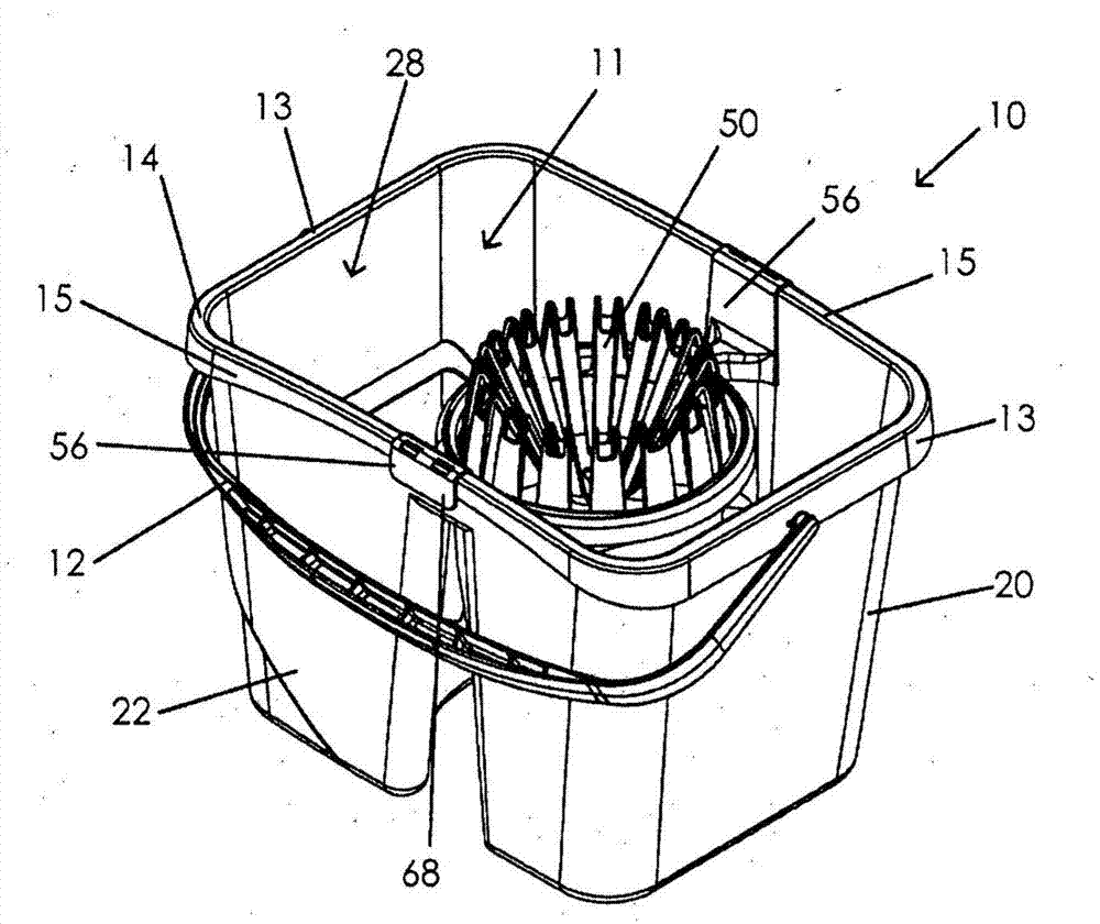
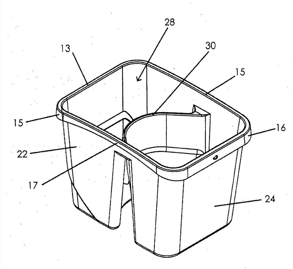
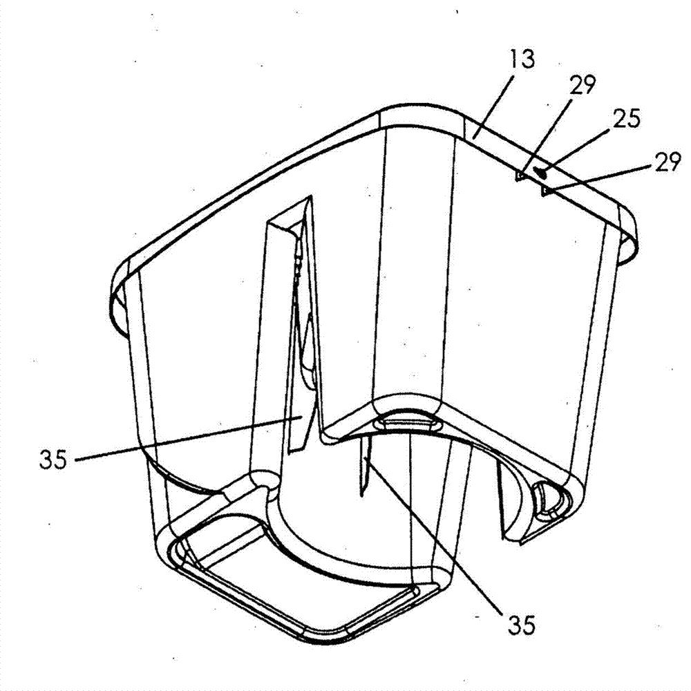
[0040] refer to Figure 1-4 , shows a mop bucket 10 according to an embodiment of the present invention. The mop bucket 10 is made of polypropylene.

[0041] The mop bucket 10 is composed of a bucket 20 and a wringer 50 . The top opening 11 of the bucket 20 is rectangular with a short side 13 and a long side 15 . A rectangular skirt 16 projects downwardly from the side 14 of the tub 20 . The skirt 16 has a constant width along the short side 13 but varies along the long side 15 . In particular, the skirt 16 tapers towards a smaller width 17 approximately in the middle of the long side 15 .

[0042] Longitudinal sidewalls 22 and transverse sidewalls 24 extend downwardly from the long side 13 and short side 15 respectively and terminate in the floor 16 . The floor 16 , side walls 22 and 24 and top opening 11 define an interior volume 28 of the bucket 20 .

[0043] A handle 12 is attached to the middle of each short side 13 and extends along the length of the long side 15 ....


PUM


Abstract

The present invention relates to a mop bucket (10) that comprises a floor (26) and side walls (22, 24) that project upwardly from the floor (26). The floor (26) and side walls (22,24) define an interior volume (28). The floor (26) opens into a cavity (32) that is provided in the interior volume (28). A wringer (50) can be suitably attached to the bucket (50) either within or above the interior volume (28). The cavity is suitably shaped to allow a wringer from a like mop bucket to be located in the cavity (32)when the like bucket is stacked on top of the mop bucket (10). This allows mop buckets to be easily stacked one on top of the other, in a space-efficient manner with the wringer attached.

Description

technical field [0001] The present invention relates to a mop bucket. In particular, the invention relates to a mop bucket with an attachable wringer. Background technique [0002] Any discussion of documents, procedures, materials, devices, articles and the like in this specification is included solely for the purpose of providing a context for the present invention. It does not imply or represent that, because any of these matters existed in Australia or elsewhere before the priority date of each claim of this application, it is considered to form part of the prior art base or to be of the relevant field to the present invention common knowledge. [0003] The mop bucket is composed of a container and a wringer for wringing the head of the mop placed in the container. Wringers fall into two broad categories: those that require manual operation (such as the well-known foot-driven drum assembly); and those that require only the manipulation of a mop to operate. [0004] A...

Claims


Application Information

Patent Timeline
Patent Type & Authority Applications(China)
IPC IPC(8): A47L13/58B65D25/28
CPCA47L13/58A47J47/18
Inventor 弗兰基·颜卡尔·兰德洛维克
Owner E D OATES
Learn More