Overcurrent protection device of circuit breaker

A protection device and over-current technology, applied in the direction of protection switch operation/release mechanism, etc., can solve the problems of weakening the magnetization of the iron core, shaking of the moving iron core, ejector rod, reducing clapping force, etc., to reduce vibration and improve product use The effect of life and stability improvement

Active Publication Date: 2017-04-05
FORETECH ELEC APP JIANGSU CORP
View PDF5 Cites 0 Cited by
  • Summary
  • Abstract
  • Description
  • Claims
  • Application Information

AI Technical Summary

Problems solved by technology

[0003] However, the electromagnetic system of this circuit breaker overcurrent protection device relies on the moving and static iron cores magnetized by the fault current to generate a clapping force to overcome the linear spring force, and continuously increase or maintain the fault current to push the push rod top. The operating mechanism is forced to trip to realize the overcurrent protection action; but because the displacement of the pressure spring within the working range is linearly proportional to the force value, the overcurrent protection action value of this type of structural product is usually a wide range. (such as: 5 times -10 times the rated current or 10 times ± 20%), and in the application of AC products, there will also be unstable phenomena of moving iron core and ejector rod shaking (due to the alternating positive and negative of AC current and There is a phenomenon that the current crosses zero, and when the current crosses zero, it will quickly and greatly weaken its magnetization on the iron core, thereby reducing the clapping force between the two. At this time, the iron core and the push rod will be under the return force of the spring Back down; when the current starts to increase again in the alternating cycle, the clapping force is gradually restored, and the clapping position is restored, so the jitter generated in the alternating current)

Method used


Image

  • Overcurrent protection device of circuit breaker
  • Overcurrent protection device of circuit breaker
  • Overcurrent protection device of circuit breaker

Examples


Embodiment Construction

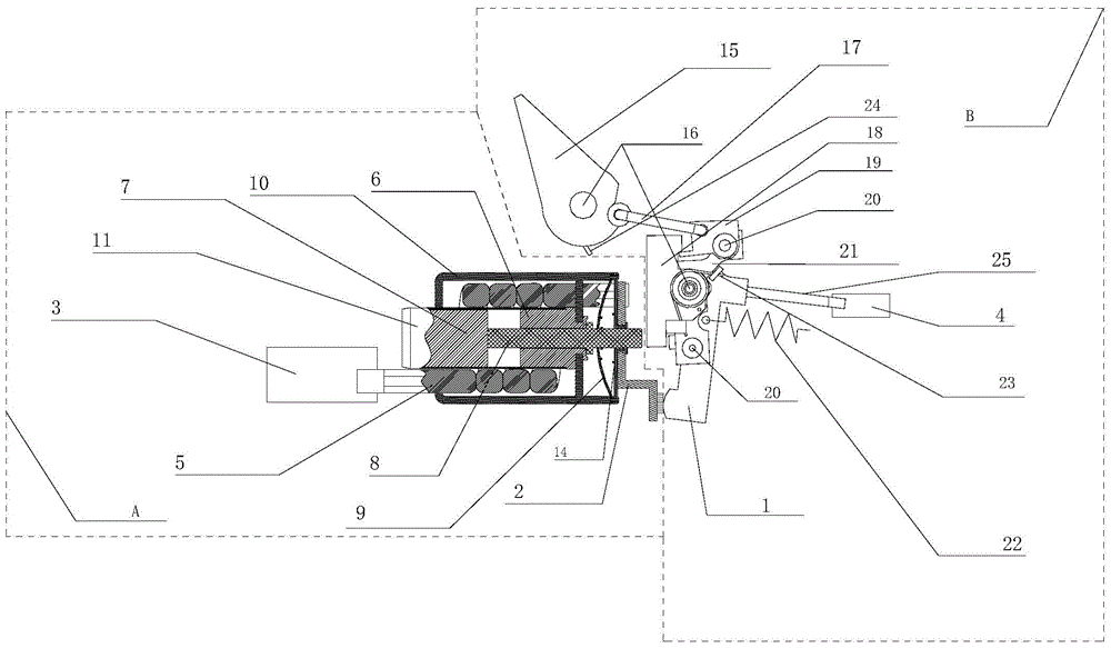
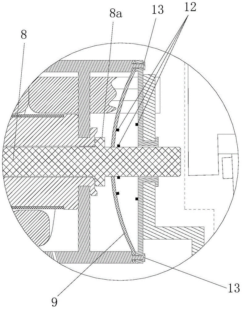
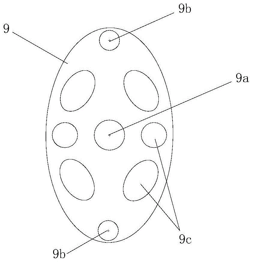
[0024] Figure 1 ~ Figure 3 A specific embodiment of the circuit breaker overcurrent protection device of the present invention is shown. The same as the traditional circuit breaker overcurrent protection device, the protection device also includes an electromagnetic system A and an operating mechanism B that cooperate with each other, wherein the electromagnetic system A includes a static contact 2, an incoming line terminal 3 electrically connected to the static contact 2, a coil 5 connected in series between the incoming line terminal 3 and the associated static contact 2, and a coil 5 electromagnetically matched to the coil 5. Static iron core 6 and moving iron core 7. The structure of the operating mechanism B is the same as the traditional structure. It consists of a moving contact 1, a handle 15, two fixed rotating shafts 16, a lever 17, a lock 18, a jumper 19, a movable rotating shaft 20, a bracket 21, and a tension spring. 22. Outlet terminal 4, first torsion spring ...


PUM


Abstract

The invention discloses an overcurrent protection device for a circuit breaker. The overcurrent protection device for the circuit breaker comprises an electromagnetic system and an operation system which are mutually matched; the electromagnetic system comprises a static contact, a wire inlet end which is electrically connected with the static contact, a coil which is in tandem connection between the wire inlet end and the static contact and a static iron core and a dynamic core which are electromagnetically matched with the coil; the operation mechanism comprises a dynamic contact which is matched with the static contact and a wire outlet end which is electrically connected with the dynamic contact; a push rod which can get close to or far from the operation mechanism along with the dynamic iron core and matched with the operation mechanism in a linkage mode is fixed on the dynamic iron core; an elastic piece is connected to the push rod; two opposite ends of the elastic piece and the static contact are relatively fixed. The overcurrent protection device for the circuit breaker can improve the movement speed and the stability of the circuit breaker during overcurrent protection.

Description

technical field [0001] The invention relates to the field of circuit breakers, in particular to an overcurrent protection device for a circuit breaker. Background technique [0002] In the traditional circuit breaker overcurrent protection device, there is a compression spring between the static iron core and the moving iron core in the electromagnetic system. The static iron core makes it overcome the stress of the compression spring and snaps it together instantly, pushes the push rod out and pushes the lock to overcome the stress of the torsion spring to release the jumper. At this time, the operating mechanism will move under the tension of the tension spring, The separation of the static contacts completes the opening of the overcurrent protection. After completion, the operating mechanism will reset under the stress of the first torsion spring and the second torsion spring to prepare for the second closing. [0003] However, the electromagnetic system of this circuit...

Claims


Application Information

Patent Timeline
Patent Type & Authority Patents(China)
IPC IPC(8): H01H71/24H01H71/68
CPCH01H71/24H01H71/68
Inventor 赵鹤薛涵宋成爱卜永祥徐宝江
Owner FORETECH ELEC APP JIANGSU CORP
Why Eureka
Try Eureka