
A Discharge Phenomenon Observation Method in Gas Discharge Test

A discharge phenomenon and gas discharge technology, applied in the control of exposure, instruments, optics, etc., can solve the problems of small practical scope, wrong judgment, difficult to use, etc., and achieve the effect of reliable application scope.

Active Publication Date: 2018-10-09
WUHAN UNIV
View PDF5 Cites 0 Cited by
  • Summary
  • Abstract
  • Description
  • Claims
  • Application Information

AI Technical Summary

Problems solved by technology

During the discharge test, the observation of the arc attachment point (the object hit by the simulated lightning) and the discharge path is the most important part. In the simulated lightning strike test, the discharge time is on the order of microseconds, and it is very easy for observers to miss the moment of discharge or make mistakes in judgment. Therefore, relying on naked eye observation will bring great errors to the test results; very few qualified scholars use high-speed cameras and other auxiliary equipment. Optoelectronic equipment is used to observe the detailed development process of the leader (streamer) in the long air gap discharge, but this kind of equipment is extremely expensive. For general discharge tests, it is not necessary to observe the detailed development process of the leader (streamer) during the discharge process. Just pay attention to the arc attachment point (the object hit by the simulated lightning) and the discharge path, and this kind of equipment is limited by the test conditions, the debugging process in the test preparation stage is cumbersome, it is difficult to get started, the practical range is small, and the use effect in the strong light environment is extremely ineffective ideal
Therefore, there are still great deficiencies and blind spots in the existing observation methods

Method used


Image

  • A Discharge Phenomenon Observation Method in Gas Discharge Test

Examples


Embodiment

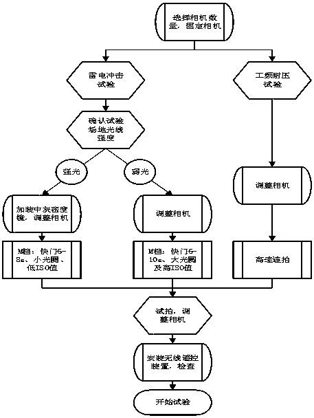
[0018] The main work of this observation method is completed in the test preparation stage before the start of the discharge. After the test starts, only the wireless remote control device is used to control the camera to take pictures.

[0019] 1. Select the number and placement of cameras

[0020] Generally, one commercially available SLR camera can meet the test observation requirements. If the test has special requirements for three-dimensional observation, three cameras and three tripods are required. Similarly, three wireless signal receiving devices are also required. The location of the camera depends on the site conditions. It is recommended to place it in the control room to facilitate real-time viewing of photos and coordination and communication among test participants.

[0021] 2. Install an adjustable neutral density mirror

[0022] The neutral gray density mirror plays the role of reducing light. When testing in an outdoor test site (strong light environment) ...


PUM


Abstract

The invention relates to a discharge phenomenon observation method in a gas discharge test, using single or multiple single-lens reflex viewfinder cameras as the main observation tool, with the help of adjustable neutral density mirrors, wireless remote control devices and tripod pairs during the day or at night Discharge paths and arc attachment points are accurately recorded from different angles during high-voltage discharge tests carried out in indoor test chambers or outdoor test fields. The method is to decide whether to install a neutral density mirror in front of the camera lens according to the light intensity of the test site, and reasonably set the relevant parameters of the camera and adjust the neutral density mirror according to the test conditions, connect the wireless signal receiver to the camera, and use the wireless signal to transmit The device controls the camera to capture the discharge phenomenon. This observation method can accurately record the discharge path and arc attachment point in the gas discharge test under various conditions. This method is economical and reliable, and can solve the problem of unobservable or inaccurate relying on the naked eye and other observation methods in the current high-voltage test.

Description

technical field [0001] The invention relates to a method for observing discharge phenomena in gas discharge tests, in particular to a method for observing discharge phenomena in gas discharge tests under various complex test conditions. Background technique [0002] Lightning strike is one of the main reasons for the failure of transmission lines and power equipment. Therefore, long air gap discharges are often used in laboratories to simulate natural lightning to study the lightning shielding performance of transmission lines; in external insulation tests, discharge tests are also necessary. During the discharge test, the observation of the arc attachment point (the object hit by the simulated lightning) and the discharge path is the most important part. In the simulated lightning strike test, the discharge time is on the order of microseconds, and it is very easy for observers to miss the moment of discharge or make mistakes in judgment. Therefore, relying on naked eye obs...

Claims


Application Information

Patent Timeline
Patent Type & Authority Patents(China)
IPC IPC(8): G03B7/00
Inventor 鄂盛龙安韵竹王羽文习山蓝磊刘宗喜徐碧川陈文广文豹陈子涵戴敏李志军叶奇明
Owner WUHAN UNIV
Learn More