
Appliance for removing oil slick on surface of soap

An appliance and oil slick technology, which is applied in the field of kitchen appliances, can solve problems such as affecting soup, affecting the taste of soup, and scalding hands with steam, and achieves the effects of simple structure, avoiding steam scalding, and convenient use by hand.

Inactive Publication Date: 2015-04-08
重庆市荣昌区粤兴不锈钢有限公司
View PDF0 Cites 0 Cited by
  • Summary
  • Abstract
  • Description
  • Claims
  • Application Information

AI Technical Summary

Problems solved by technology

[0002] In daily life, people tend to cook various soups such as chicken soup, ribs soup, hoof soup, three delicacies soup or tonic stew. Usually when making soup, there will be a layer of oil floating on the surface of the soup. Many people because of This layer of oil makes the soup too greasy and unwilling to drink, and some people cannot drink soup with too much oil, such as obese people, elderly people with hyperlipidemia, etc. In addition, the existence of this layer of oil will also affect the taste of the soup. Usually, during the soup making process, the slick oil on the surface of the soup should be removed in time, so as not to affect the taste of the soup. Usually, the oil-absorbing paper is used to absorb it repeatedly or use a spoon to scoop it up and pour it out. These methods are time-consuming and the effect of oil removal is not good. Well, in addition, often due to the high temperature of the soup, the steam generated will burn your hands, usually resulting in the inability to remove the slick oil on the surface of the soup in time during the soup making process

Method used


Image

  • Appliance for removing oil slick on surface of soap
  • Appliance for removing oil slick on surface of soap

Examples


Embodiment Construction

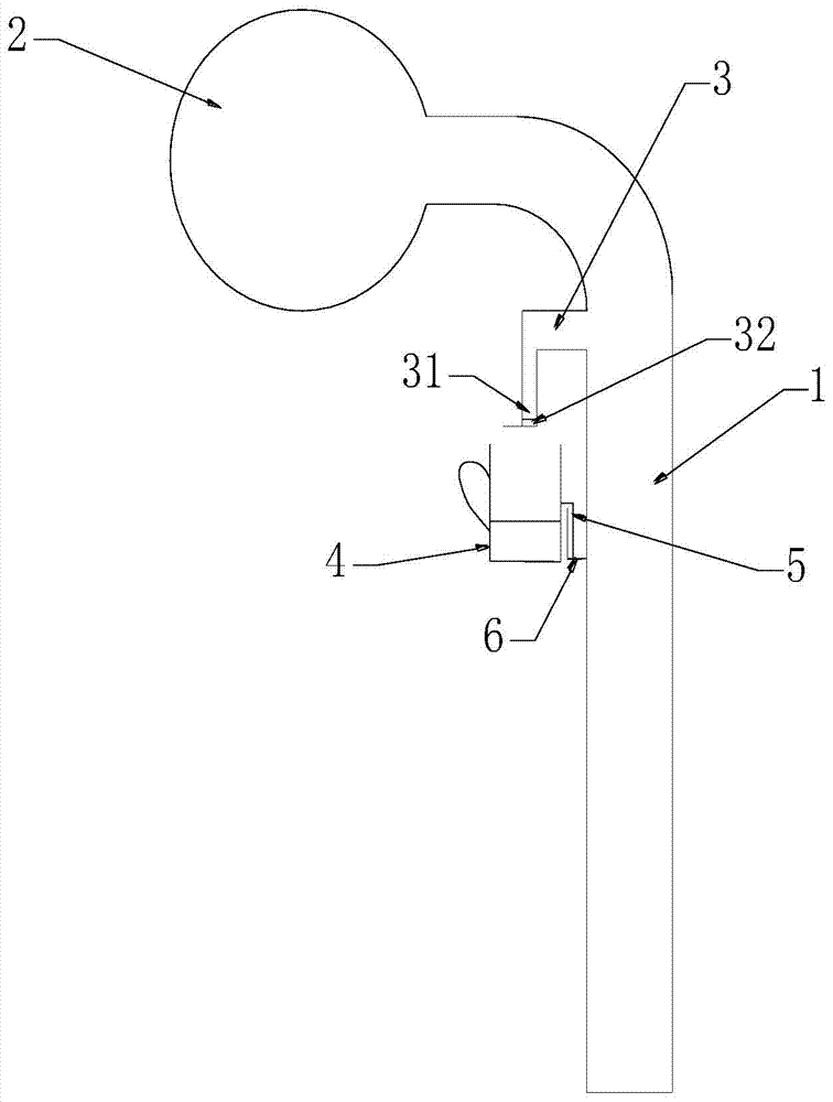
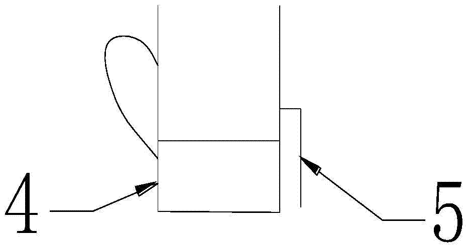
[0014] The present invention will be described in detail below in conjunction with accompanying drawing, as Figure 1-2 Shown:

[0015] A device for removing floating oil on the soup surface of the present invention comprises a transparent pipe 1 and a rubber extruding ball 2, the upper end of the transparent pipe 1 is bent, and the rubber extruding ball 2 is connected with the upper port of the transparent pipe 1, the The lower port of the transparent pipe 1 is the soup inlet. The device has a simple structure. Squeeze the rubber ball and then loosen it slowly. It can suck the slick oil on the surface of the soup into the transparent pipe from the soup inlet, and at the same time suck part of the soup. However, because the specific gravity of the slick oil is smaller than that of water, The floating oil sucked into the transparent pipe is at the upper end of the soup, while the soup is at the lower end, then gently squeeze the rubber extrusion ball to discharge the soup suck...


PUM


Abstract

The invention discloses an appliance for removing oil slick on the surface of soap. The appliance comprises a transparent tube and a rubber extrusion ball, wherein the upper end of the transparent tube is bent; the rubber extrusion ball is connected with an upper end opening of the transparent tube; and a lower end opening of the transparent tube is a soap inlet. The appliance is simple in structure, the rubber extrusion ball is extruded and is released slowly, then the oil slick on the surface of the soup can be sucked into the transparent tube from the soap inlet, simultaneously, a part of soup can also be sucked into the transparent tube, but because the specific gravity of the oil slick is smaller than that of water, the oil slick sucked into the transparent tube stays on the upper surface of the soup, the soup stays on the lower surface of the oil slick, the rubber extrusion ball is extruded slightly, the soup sucked into the transparent tube can be drained to a pot, then the appliance moves away from the pot, the rubber extrusion ball is extruded again, and the oil slick sucked into the transparent tube can be drained. Because the upper end of the transparent tube is bent, the rubber extrusion ball can be positioned beside the soup pot and can be convenient to grip, and a hand of a user is prevented from being scalded by hot steam in the soup pot. By the appliance, the hand of the user cannot be scalded in a soup cooking process.

Description

technical field [0001] The invention relates to a kitchen utensil, in particular to an utensil capable of removing slick oil on the soup surface conveniently and quickly. Background technique [0002] In daily life, people tend to cook various soups such as chicken soup, ribs soup, hoof soup, three delicacies soup or tonic stew. Usually when making soup, there will be a layer of oil floating on the surface of the soup. Many people because of This layer of oil makes the soup too greasy and unwilling to drink, and some people cannot drink soup with too much oil, such as obese people, elderly people with hyperlipidemia, etc. In addition, the existence of this layer of oil will also affect the taste of the soup. Usually, during the soup making process, the slick oil on the surface of the soup should be removed in time, so as not to affect the taste of the soup. Usually, the oil-absorbing paper is used to absorb it repeatedly or use a spoon to scoop it up and pour it out. These m...

Claims


Application Information

Patent Timeline
Patent Type & Authority Applications(China)
IPC IPC(8): A47J43/28
Inventor 林浩
Owner 重庆市荣昌区粤兴不锈钢有限公司
Learn More