
Control method of line control brake based on flow control

A flow control and flow technology, applied in the direction of brakes, hydraulic brake transmissions, etc., can solve problems such as large differences in brake pedal input, unclear physical meaning of control algorithm design, and PID control technology that cannot meet control requirements.

Active Publication Date: 2015-04-01
ZHEJIANG WANXIANG PRECISION IND +1
View PDF3 Cites 3 Cited by
  • Summary
  • Abstract
  • Description
  • Claims
  • Application Information

AI Technical Summary

Problems solved by technology

However, the existing braking system control has the following disadvantages: 1. The physical meaning of the control algorithm design is not clear, and the design process depends on on-site parameter debugging; Do the calculations, but not the controls
If the dead zone is set too small in the software switch control, it will inevitably lead to system pressure jitter, and the pedal feel is not good, and if the dead zone is set too large, the control accuracy will not be high; 3. PID control technology is aimed at a single system parameter, A better pressure control effect can be obtained, but under different drivers and different working conditions, the brake pedal input varies greatly, and the parameters of different products also have large discreteness, and the PID control technology cannot meet the control requirements; 4. Fixed The PID control of parameters cannot meet the control requirements in all situations, and cannot meet the actual requirements in the performance indicators of overshoot and response time, while the adaptive PID algorithm requires a lot of testing and debugging time

Method used


Image

  • Control method of line control brake based on flow control
  • Control method of line control brake based on flow control
  • Control method of line control brake based on flow control

Examples


Embodiment Construction

[0043] The present invention will be further described in detail below in conjunction with the examples, the following examples are explanations of the present invention and the present invention is not limited to the following examples.

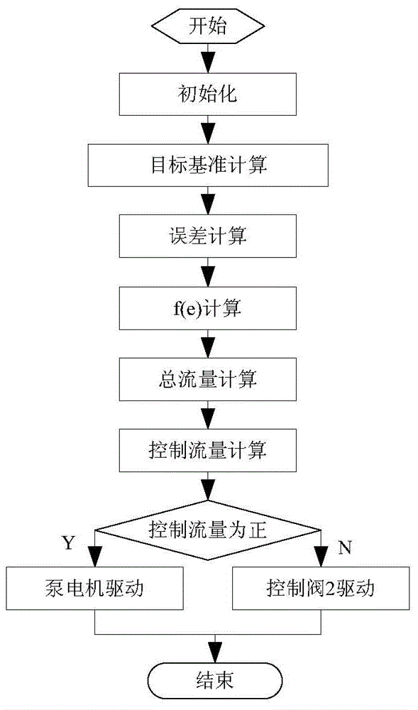
[0044] The brake-by-wire control method based on flow control provided by the present invention, such as figure 2 shown, including the following steps:

[0045] Step 1: Control Target Baseline Calculation

[0046] The control targets are the system pressure (ie the pressure at the left side of the brake master cylinder 51 ) and the pedal reaction force in the dynamic process.

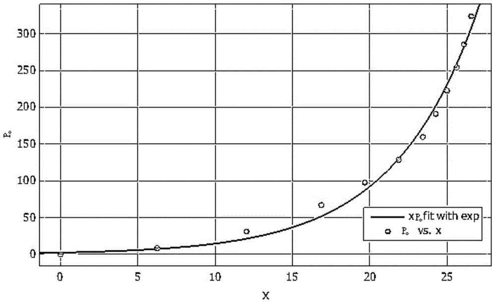
[0047] The relationship between system pressure and pedal displacement is obtained by simulating a conventional braking system, such as image 3 As shown, its shape is similar to a parabola. In the present invention, an exponential curve is used for fitting calculation, and the calculation formula is as follows:

[0048] P 0 =ae bx

[0049] Among them, P 0 is ...


PUM


Abstract

The invention discloses a control method of line control brake based on flow control, by considering the system pressure and the pedal feedback force error and combining the state equation of the system based on the flow control, the control has multi-parameter characteristic, non-linear characteristic, prediction control characteristic and pressure increasing and reducing accordance characteristic, at the premise of meeting the pressure control requirement, the pedal feedback force is stable, the control algorithm is simple and the control adaptability is strong.

Description

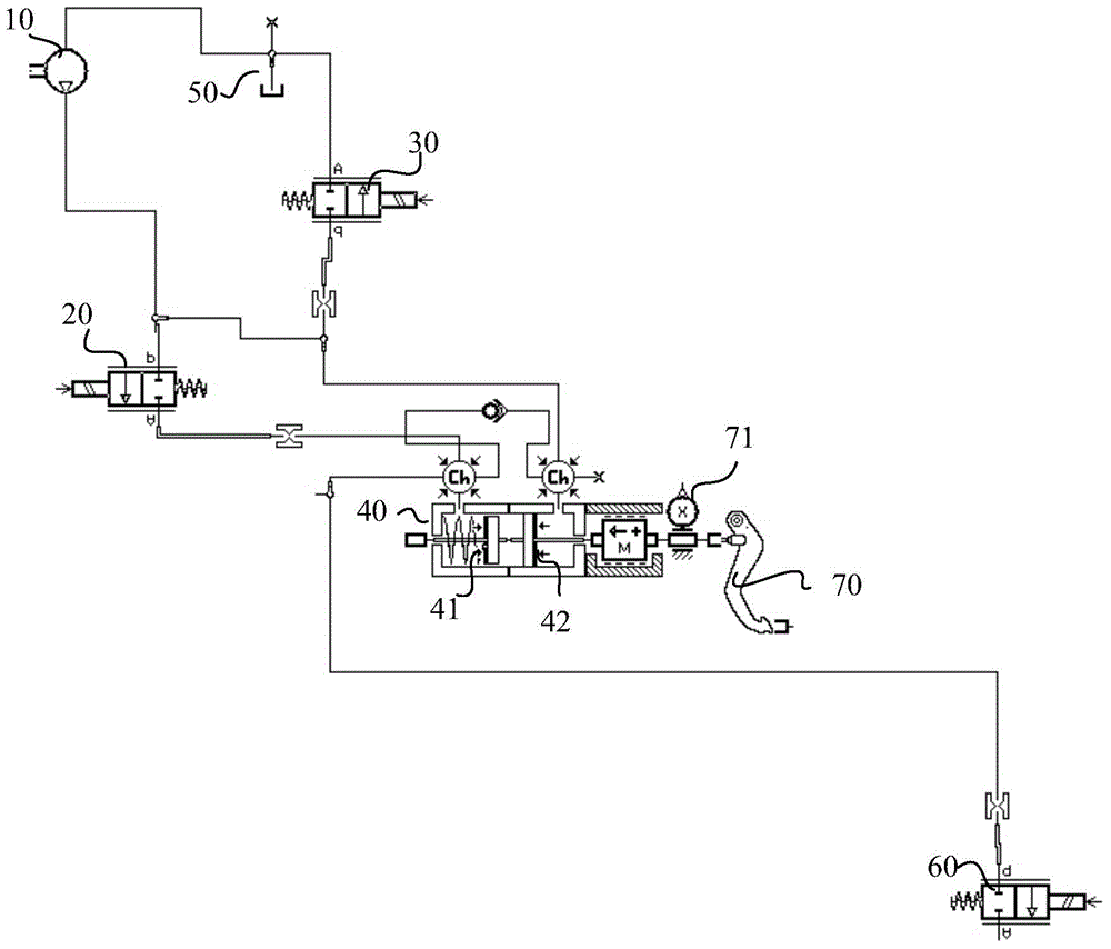
technical field [0001] The invention relates to a brake-by-wire control method, in particular to a flow control-based brake-by-wire control method that comprehensively considers system pressure and pedal feedback force errors. Background technique [0002] The schematic diagram of the existing wire-controlled parking brake system is as follows: figure 1 As shown, the left side 41 of the brake master cylinder is connected to the plunger pump 10 through the first control valve 20, the right side 42 of the brake master cylinder is connected to the brake fluid tank 50 through the second control valve 30, and the ABS booster valve 60 is connected to the brake pump. The left side 41 of the master cylinder, the pedal 70 is provided with a displacement sensor 71 for detecting the displacement of the pedal. In the prior art parking brake system by wire, the system pressure is usually taken as the control object, and the piston pump motor speed or the opening time of the system press...

Claims


Application Information

Patent Timeline
Patent Type & Authority Applications(China)
IPC IPC(8): B60T11/10
CPCB60T11/10B60T2220/04B60T2220/06
Inventor 刘长运刘伟潘劲吴志强
Owner ZHEJIANG WANXIANG PRECISION IND
Learn More