
motor

A circuit board and conductive part technology, applied in electrical components, electromechanical devices, electric components, etc., can solve the problem that the long-term effectiveness of the electrical connection between the bearing brackets on both sides cannot be achieved, the electrical connection between the bearing brackets on both sides fails, and the contact resistance of the conductive tape increases. Large and other problems, to achieve the effect of preventing electrical corrosion of bearings, ensuring long-term effectiveness, and easy operation

Active Publication Date: 2017-11-10
GUANGDONG WELLING ELECTRIC MACHINE MFG
View PDF4 Cites 0 Cited by
  • Summary
  • Abstract
  • Description
  • Claims
  • Application Information

AI Technical Summary

Problems solved by technology

Specifically, the two ends of the conductive tape are respectively bonded to the bearing brackets on both sides. In this way, the electrical connection of the bearing brackets on both sides can be realized through the conductive tape, which can alleviate the electric corrosion of the bearings to a certain extent. There are still the following deficiencies in the application: 1) The installation and fixation of the conductive tape is realized solely by the bonding of the conductive tape and the bearing bracket, and the stability and reliability of the installation is low; 2) In order to realize the bonding of the conductive tape and the bearing bracket, it is necessary to The bearing bracket has an exposed part and the exposed part needs to be cleaned of oil and other operations, and the bonding operation process is complicated; 3) After the motor has been in operation for a long time, the conductive tape may appear to be less stable due to aging, thus The contact resistance of the conductive tape will increase or even fall off, which will lead to the failure of the electrical connection of the bearing brackets on both sides, and finally the long-term effectiveness of the electrical connection of the bearing brackets on both sides cannot be realized.

Method used


Image

  • motor
  • motor
  • motor

Examples


Embodiment Construction

[0031] In order to make the object, technical solution and advantages of the present invention clearer, the present invention will be further described in detail below in conjunction with the accompanying drawings and embodiments. It should be understood that the specific embodiments described here are only used to explain the present invention, not to limit the present invention.

[0032] It should be noted that when an element is referred to as being “fixed” or “disposed on” another element, it may be directly on the other element or there may be an intervening element at the same time. When an element is referred to as being "connected to" another element, it can be directly connected to the other element or intervening elements may also be present. It should also be noted that the orientation terms such as left, right, up, down, top, and bottom in this embodiment are only relative concepts or refer to the normal use state of the product, and should not be regarded as havin...


PUM


Abstract

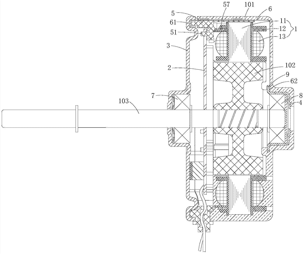
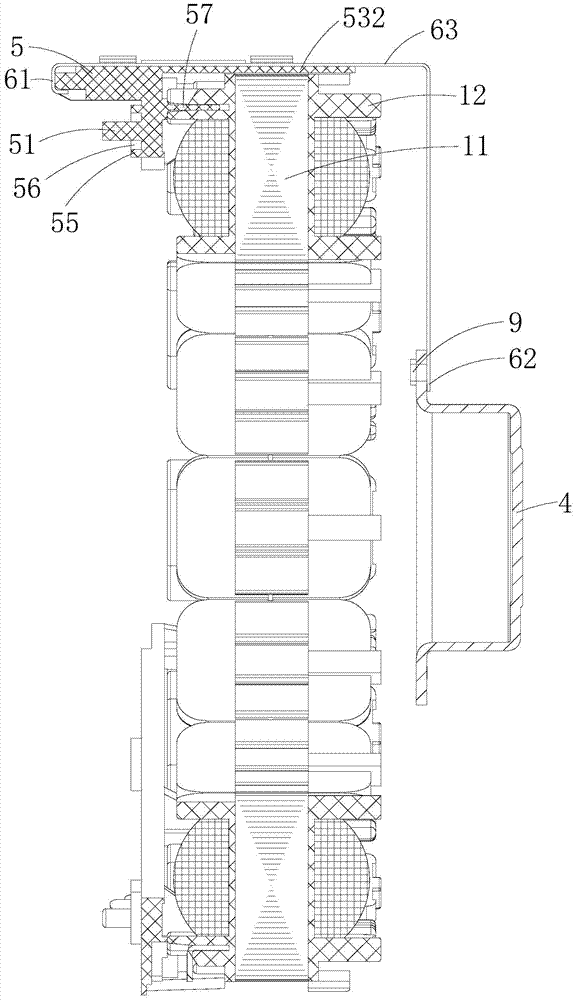
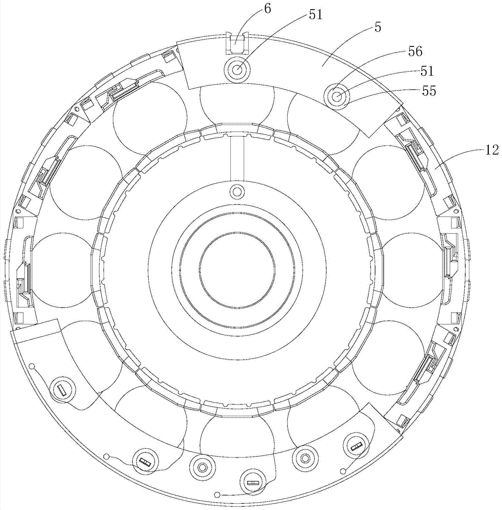
The invention is applicable to the field of motors, and discloses a motor, which includes a stator assembly, a circuit board, and a first bearing bracket and a second bearing bracket respectively arranged on both sides of the stator assembly; it also includes an insulating bracket and a fixing bracket installed on the stator assembly The metal conductive member on the insulating support and the two ends are electrically connected to the first bearing support and the second bearing support respectively. The insulating support is provided with a positioning column, and the circuit board is provided with a positioning hole. The circuit board is supported on the insulating support, and the positioning The column is arranged in the positioning hole. The present invention realizes the electrical connection between the first bearing bracket and the second bearing bracket through the arrangement of metal conductive components, and ensures the long-term effectiveness of the electrical connection between the first bearing bracket and the second bearing bracket; at the same time, its The arrangement of the insulating bracket can not only realize the locking and fixing of the metal conductive member, but also realize the support and positioning of the circuit board, which is beneficial to reduce the number of parts of the motor.

Description

technical field [0001] The invention belongs to the field of motors, in particular to a motor. Background technique [0002] Conventional plastic-encapsulated brushless DC motors generally have the problem of electric corrosion of bearings. In order to solve this technical problem, the prior art proposes a technical proposal of installing conductive tape between the bearing brackets on both sides. Specifically, the two ends of the conductive tape are respectively bonded to the bearing brackets on both sides. In this way, the electrical connection of the bearing brackets on both sides can be realized through the conductive tape, which can alleviate the electric corrosion of the bearings to a certain extent. There are still the following deficiencies in the application: 1) The installation and fixation of the conductive tape is realized solely by the bonding of the conductive tape and the bearing bracket, and the stability and reliability of the installation is low; 2) In orde...

Claims


Application Information

Patent Timeline
Patent Type & Authority Patents(China)
IPC IPC(8): H02K11/00H02K5/16H02K11/20
CPCH02K5/161H02K7/083H02K11/00H02K11/40
Inventor 李国雄唐剑武李虎李万周庆杰
Owner GUANGDONG WELLING ELECTRIC MACHINE MFG
Learn More