Vehicle-mounted terminal intelligent power supply system

A technology of vehicle terminal and power supply system, applied in current collectors, electric vehicles, electrical components, etc., can solve the problems of increased power loss, battery damage, rising to about 15 mA, etc., to reduce loss and ensure smooth operation. Effect

Inactive Publication Date: 2015-03-25
JIANGSU TIANAN SMART SCI & TECH
View PDF5 Cites 4 Cited by
  • Summary
  • Abstract
  • Description
  • Claims
  • Application Information

AI Technical Summary

Problems solved by technology

In this case, if the car is not ignited and charged for a long time, the power of the car battery itself will be exhausted, which will affect the use of equipment and the car itself.
It will even affect the ignition of the car in the future, especially in the existing car terminals, the use of smart terminals with GPRS / 3G communication functions, the standby current rises from the ordinary 3 milliamperes to about 15 milliamperes, which is harmful to the battery power consumption increased
Subsequently, the original power in the car battery will also shorten the support time for the car equipment in standby mode, and once the battery is seriously depleted, it will not only affect the use of the car itself, but may also cause irresistible damage to the battery. undo damage
[0003] In summary, seeking a method or device to solve the technical problem of increased power loss in the existing standby mode has become an urgent problem to be solved by those skilled in the art

Method used


Image

  • Vehicle-mounted terminal intelligent power supply system
  • Vehicle-mounted terminal intelligent power supply system

Examples


Embodiment Construction

[0023] The present invention will be described in further detail below according to the drawings and embodiments.

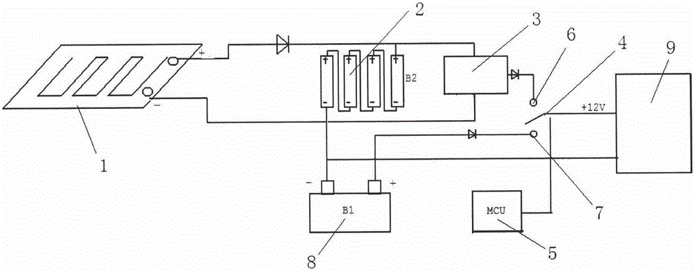
[0024] Such as figure 1 As shown, a vehicle-mounted terminal intelligent power supply system described in an embodiment of the present invention includes:

[0025] solar panel 1;

[0026] A storage battery 2, the storage battery 2 is connected to the solar battery panel 1, and is charged by the solar battery panel 1;

[0027] A boost circuit 3, one end of the boost circuit 3 is connected to the battery 2, and the other end is provided with a first connection contact 6,

[0028] A power supply switch 4, the movable end of the power supply switch 4 can be connected to the first connection contact 6, and the fixed end is connected to the vehicle-mounted terminal 9;

[0029] The micro control unit 5 is connected with the power supply switch 4 to control the power supply switch 4 .

[0030] In the above embodiment, by adding solar panels to charge the battery, sup...


PUM


Abstract

A vehicle-mounted terminal intelligent power supply system comprises a storage battery, a boost circuit, a power supply switch and a micro control unit, wherein the storage battery is connected with a solar panel and can be charged through the solar panel, one end of the boost circuit is connected with the storage battery, the other end of the boost circuit is provided with a first connection contact, the movable end of the power supply switch is connected with the first connection contact in an on-off mode, the fixed end of the power supply switch is connected with a vehicle-mounted terminal, and the micro control unit is connected with the power supply switch and is used for controlling the power supply switch. According to the vehicle-mounted terminal intelligent power supply system, complementary power supply is achieved at any time by additionally arranging the solar panel to charge the storage battery, the system is controlled through the micro control unit, the power supply switch is made to be connected with the first contact point of the boost circuit when the electric quantity in the storage battery is sufficient or the electric quantity in a vehicle-mounted storage battery is reduced to a certain value, power is supplied to the vehicle-mounted terminal through the storage battery, loss of the vehicle-mounted storage battery is reduced, even if a vehicle is not started for a long time, power lack of the vehicle-mounted storage battery can not be caused, and smooth operation of vehicle is guaranteed.

Description

technical field [0001] The invention relates to the technical field of vehicle-mounted terminals, in particular to an intelligent power supply system for vehicle-mounted terminals that utilizes solar energy for power supply supplementation. Background technique [0002] In the prior art, due to the continuous development and updating of the automobile application technology, when the automobile is turned off, some devices of the vehicle terminal are still in the standby mode. Although the current of the on-board equipment in standby mode is very small, the total current can still reach the range of 80-100 mA, and the power consumption at this time is usually provided by the battery of the car itself. In this case, if the car is not ignited and charged for a long time, the power of the car battery itself will be exhausted, which will affect the use of the equipment and the car itself. It will even affect the ignition of the car in the future, especially in the existing car t...

Claims


Application Information

Patent Timeline
Patent Type & Authority Applications(China)
IPC IPC(8): H02J7/35
CPCH02J7/35
Inventor 罗洪郎继军曾祯
Owner JIANGSU TIANAN SMART SCI & TECH
Why Eureka
Try Eureka