A testing method of infrared touch screen algorithm based on matlab

An infrared touch screen and algorithm technology, applied in software simulation/interpretation/simulation, program control devices, etc., can solve problems such as difficult positioning of infrared touch screen system hardware, low system debugging efficiency, etc.

Inactive Publication Date: 2017-10-10
北京千里触控设备有限公司
View PDF4 Cites 0 Cited by
  • Summary
  • Abstract
  • Description
  • Claims
  • Application Information

AI Technical Summary

Problems solved by technology

[0005] In view of this, the present invention provides a MATLAB-based infrared touch screen algorithm testing method to solve the low efficiency of system debugging in the prior art, and it is not easy to locate when a problem occurs in the test is a problem with the infrared touch screen system hardware or the infrared touch screen system. problem with software

Method used


Image

  • A testing method of infrared touch screen algorithm based on matlab
  • A testing method of infrared touch screen algorithm based on matlab
  • A testing method of infrared touch screen algorithm based on matlab

Examples


Embodiment 1

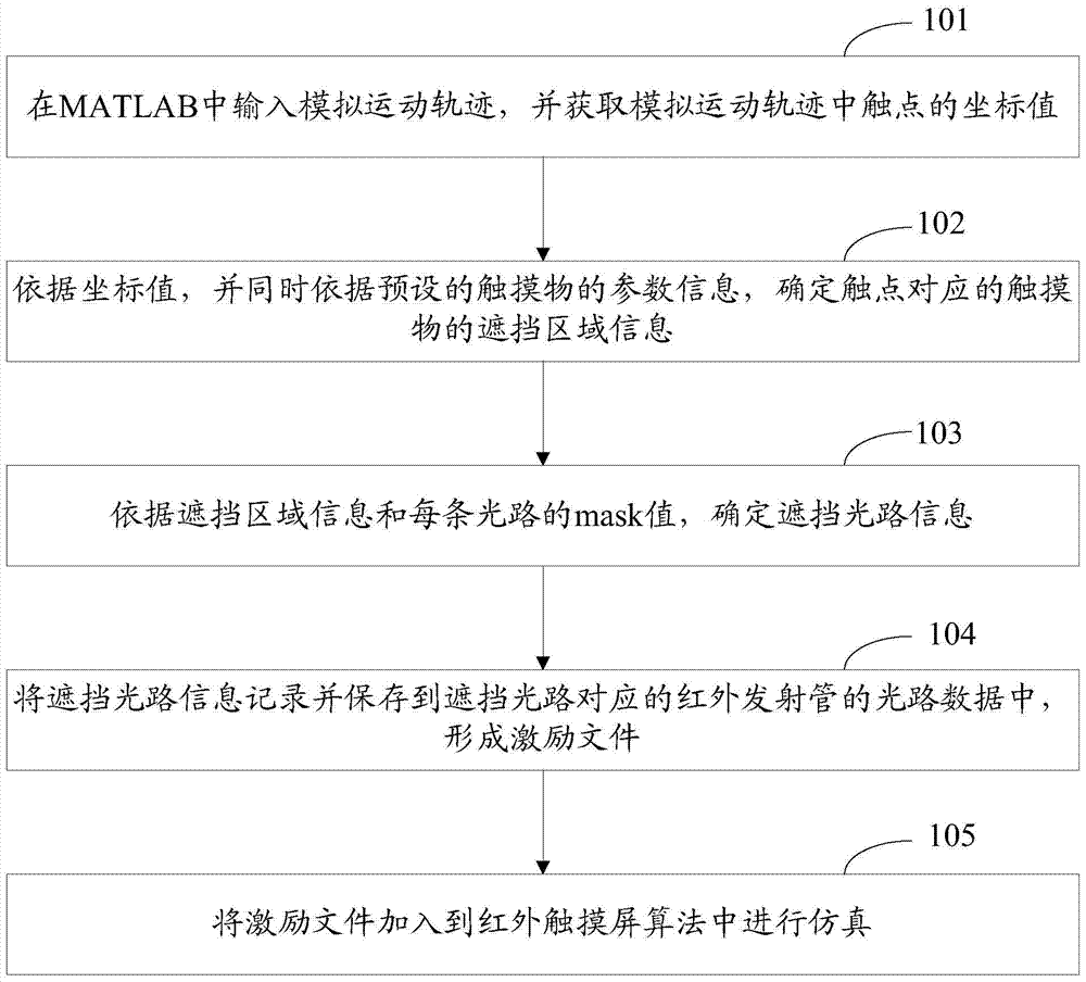
[0057] see figure 1 , which shows a flow chart of a testing method for an infrared touch screen algorithm based on MATLAB provided by the present invention. The infrared touch screen is provided with a plurality of infrared emission tubes, wherein each infrared emission tube includes a plurality of light paths, and each light path is correspondingly set with a mask (mask) value. Methods include:

[0058] Step 101, input the simulated motion trajectory in MATLAB, and obtain the coordinate values ​​of the contacts in the simulated motion trajectory.

[0059] In the present invention, the present invention is no longer limited to the hardware of the infrared touch screen system, and the user does not need to draw a line on the infrared touch screen through fingers or other opaque objects, but through MATLAB, input the simulated motion trajectory in MATLAB, and use MATLAB numerical calculation The function realizes the software input of the simulated motion trajectory.

[0060]...

Embodiment 2

[0096] Based on the above examples, please refer to Figure 6 , which shows another structural representation of a testing method based on MATLAB-based infrared touch screen algorithm provided by the present invention, including:

[0097] Step 201, input the simulated motion trajectory in MATLAB, and obtain the coordinate values ​​of the contacts in the simulated motion trajectory.

[0098] Step 202 , according to the coordinate value and at the same time according to the preset parameter information of the touch object, determine the occlusion area information of the touch object corresponding to the touch point.

[0099] Step 203: Determine information about the blocked light path according to the blocked area information and the mask value of each light path.

[0100] Step 204, record and save the blocked light path information into the light path data of the infrared emission tube corresponding to the blocked light path to form an excitation file.

[0101] Steps 201 to 2...


PUM


Abstract

A kind of testing method of the infrared touch screen algorithm based on MATLAB provided by the present invention, its infrared touch screen is provided with a plurality of infrared emitting tubes, each infrared emitting tube includes a plurality of optical paths, and each optical path is correspondingly provided with a mask value; method comprises : Input the simulated motion track in MATLAB, and obtain the coordinate value of the touch point in the simulated motion track; according to the coordinate value, and at the same time, according to the parameter information of the preset touch object, determine the occlusion area information of the touch object corresponding to the touch point; Blocking area information and the mask value of each light path determine the blocking light path information; record and save the blocking light path information to the light path data of the infrared emission tube corresponding to the blocking light path to form an excitation file; add the excitation file to the infrared touch screen algorithm simulation. Therefore, the present invention is independently performed without depending on the hardware of the infrared touch screen, and the system debugging efficiency is high.

Description

technical field [0001] The invention relates to the technical field of infrared touch screen algorithm testing, and more specifically, relates to a testing method of an infrared touch screen algorithm based on MATLAB. Background technique [0002] The infrared touch screen is composed of infrared emitting and receiving sensing elements installed on the outer frame of the touch screen, and an infrared detection network is formed on the surface of the touch screen. Specifically, the circuit board device arranged on the four sides of the infrared touch screen screen has an infrared emitting tube and an infrared receiving tube, and the infrared emitting tube and the infrared receiving tube correspond to form a horizontal and vertical infrared matrix. Any touching object can change the infrared on the contact point. And then converted into contact coordinates, and sent to CPU (Central Processing Unit, central processing unit) to realize the touch screen operation. [0003] There...

Claims


Application Information

Patent Timeline
Patent Type & Authority Patents(China)
IPC IPC(8): G06F9/455
Inventor 杨运张自能
Owner 北京千里触控设备有限公司
Why Eureka
Try Eureka