
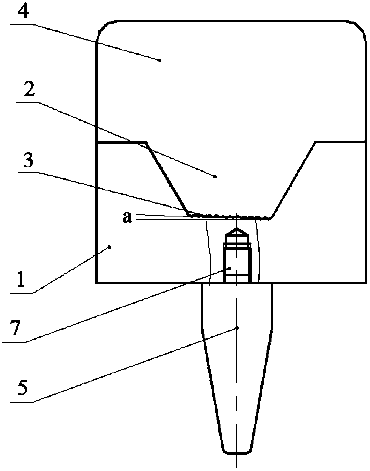
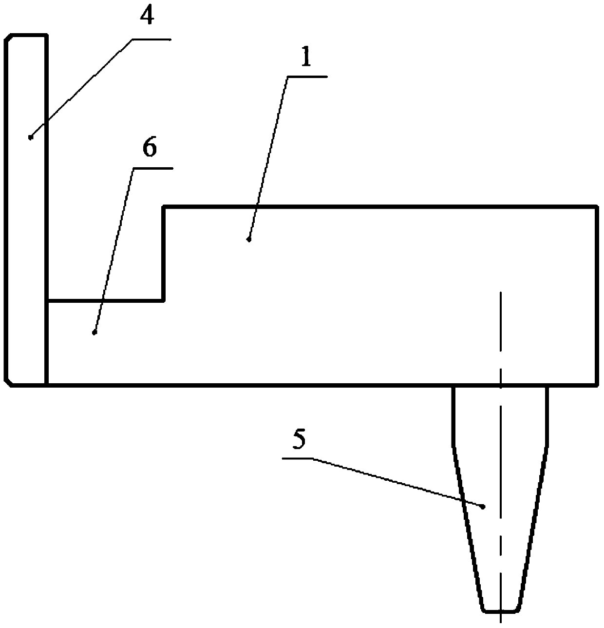
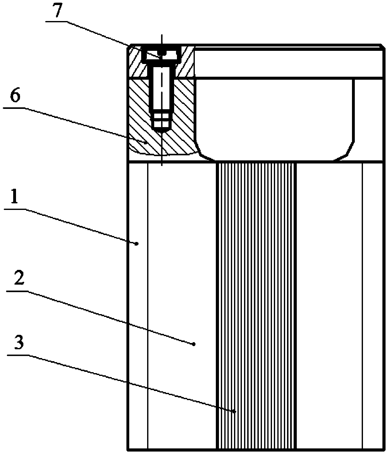
Optical fiber face plate fractal filament arranging method and filament arranging dies thereof

An optical fiber panel and mold technology, which is applied in the direction of beam optical fibers, manufacturing tools, glass manufacturing equipment, etc., can solve the problems of reducing the service life of the picture tube, the gap of the multi-filament boundary unit filament, affecting the image clarity and air tightness, etc. Achieve improved clarity and tightness, improved performance and longevity

Active Publication Date: 2015-03-25
CHINA BUILDING MATERIALS ACAD
View PDF3 Cites 12 Cited by
  • Summary
  • Abstract
  • Description
  • Claims
  • Application Information

AI Technical Summary

Problems solved by technology

[0003] At present, the wire arrangement process of optical fiber panels is to arrange the regular hexagonal composite wires on the same horizontal plane in a vertical state, which leads to the inevitable gap between the multifilament boundary unit wires
The resulting gap affects the clarity and airtightness of the image transmission and reduces the service life of the picture tube

Method used


Image

  • Optical fiber face plate fractal filament arranging method and filament arranging dies thereof
  • Optical fiber face plate fractal filament arranging method and filament arranging dies thereof
  • Optical fiber face plate fractal filament arranging method and filament arranging dies thereof

Examples


Embodiment Construction

[0044] In order to make the object, technical solution and advantages of the present invention clearer, the implementation manner of the present invention will be further described in detail below in conjunction with the accompanying drawings.

[0045] A fractal wire arrangement method for an optical fiber panel, the method comprising:

[0046] (1) drawn monofilament

[0047] Put the matched rod and tube combination into the wire drawing machine for the first wire drawing to obtain monofilament;

[0048] (2) Arranging a composite rod and drawing a composite wire

[0049] Carry out the first wire drawing of the monofilament to obtain the primary composite rod, put the primary composite rod into the wire drawing machine for the second wire drawing, and obtain the primary composite wire;

[0050] (3) Arranging secondary composite rods and drawing secondary composite wires

[0051] Put the primary composite wires into the primary composite wire wire arranging mold for the secon...


PUM

PropertyMeasurementUnit
diameteraaaaaaaaaa
sizeaaaaaaaaaa

Abstract

The invention discloses an optical fiber face plate fractal filament arranging method and filament arranging dies thereof. The method comprises the steps of (1) monofilament drawing, (2) primary composite rod arrangement and primary composite filament drawing, (3) secondary composite rod arrangement and secondary composite filament drawing and (4) plate arrangement. In the step of secondary composite rod arrangement and secondary composite filament drawing, primary composite filaments are put into a primary composite filament arranging die to carry out secondary filament arrangement to obtain secondary composite rods, the difference of two adjacent primary composite filaments in the vertical direction is made to be the radius of one unit filament when filament arrangement is carried out, and the secondary composite rods are put into a drawing machine to carry out tertiary filament arrangement to obtain secondary composite filaments. In the step of plate arrangement, the secondary composite filaments are put into a secondary composite filament arranging die to carry out tertiary filament arrangement to obtain a tailored plate. When filament arrangement is carried out, the distance of the two adjacent secondary composite filaments in the vertical direction is half of the opposite side distance of the primary composite filaments. The multifilament boundary in the optical fiber face plate made through the filament arranging method is free of clearance, the definition of image transmitting and air tightness are improved, and therefore the performance of an image tube is improved and the service life of the image tube is prolonged.

Description

technical field [0001] The invention relates to the field of optical fiber panel manufacturing, in particular to a fractal wire arrangement method for an optical fiber panel and a wire arrangement mold thereof. Background technique [0002] The optical fiber panel is a hard optical fiber component formed by a number of closely arranged optical fibers through the processes of arranging, melting, rolling, cutting, and finishing. It has the characteristics of good light collection performance, high resolution, zero optical thickness, and can transmit high-definition images without distortion. It is widely used in input and output screens of various electronic optical devices. [0003] The current fiber arrangement process of optical fiber panels is to arrange regular hexagonal composite filaments on the same horizontal plane in a vertical state, which leads to inevitable gaps between the multifilament boundary unit filaments. The resulting gap affects the clarity and airtightn...

Claims


Application Information

Patent Timeline
Patent Type & Authority Applications(China)
IPC IPC(8): G02B6/04
CPCC03B37/02G02B6/04
Inventor 冯跃冲黄康胜张敬李开宇
Owner CHINA BUILDING MATERIALS ACAD
Learn More