Eureka AIR delivers breakthrough ideas for toughest innovation challenges, trusted by R&D personnel around the world.

A cross braced energy dissipator

A technology of cross bracing and energy dissipator, which is applied in the direction of building components, earthquake resistance, etc., can solve the problems of affecting the shock absorption effect of the energy dissipator, weakening the stiffness, complex structure, etc., achieving simplicity and flexibility, and preventing buckling instability , the effect of reducing the calculation length

Active Publication Date: 2017-07-28
SOUTHEAST UNIV
View PDF14 Cites 1 Cited by
  • Summary
  • Abstract
  • Description
  • Claims
  • Application Information

AI Technical Summary

Problems solved by technology

Among them, the shear-type energy dissipator has high rigidity and is easy to control the lateral movement, but it is prone to out-of-plane buckling, resulting in pinching of the hysteretic loop, which cannot achieve full-section yield, and there are obvious stress concentrations at the corners, which are prone to early occurrence Cracks greatly weaken the fatigue life of the energy dissipator and affect the normal operation of the energy dissipator
In addition, the energy dissipation parts and fixed parts of this energy dissipator are mainly welded, and there are residual stresses, and the local residual stress may have made the material yield, thus significantly affecting the shock absorption effect of the energy dissipator
In order to solve this problem, the engineering community has proposed three solutions: 1. Welding stiffeners, this method has residual stress and deformation; 2. Slits, this method will cut off the tension field, thereby weakening the stiffness; 3. Set up another device Constrained out-of-plane deformation, the method is complex in construction

Method used


Image

  • A cross braced energy dissipator
  • A cross braced energy dissipator
  • A cross braced energy dissipator

Examples


Embodiment Construction

[0020] The present invention will be further explained below in conjunction with the accompanying drawings.

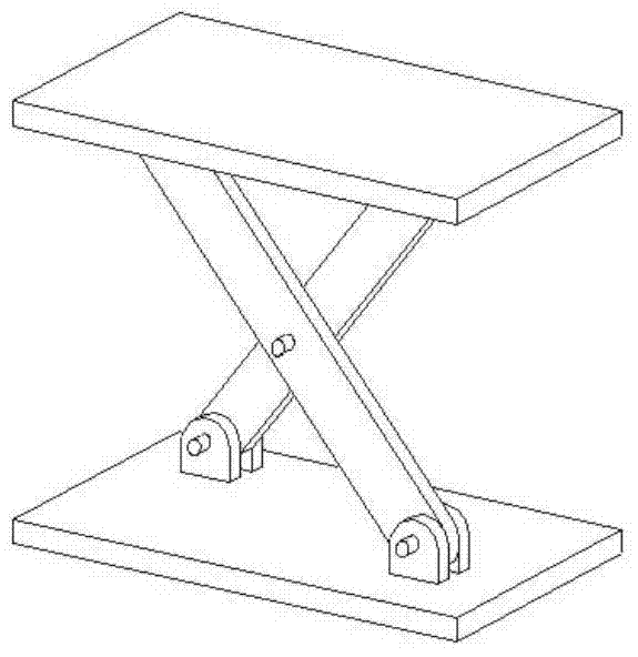
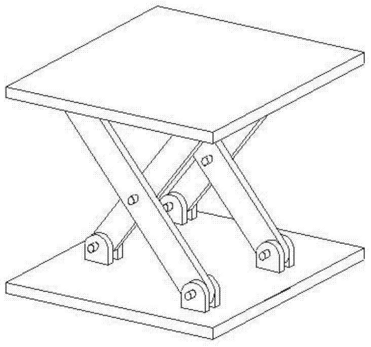
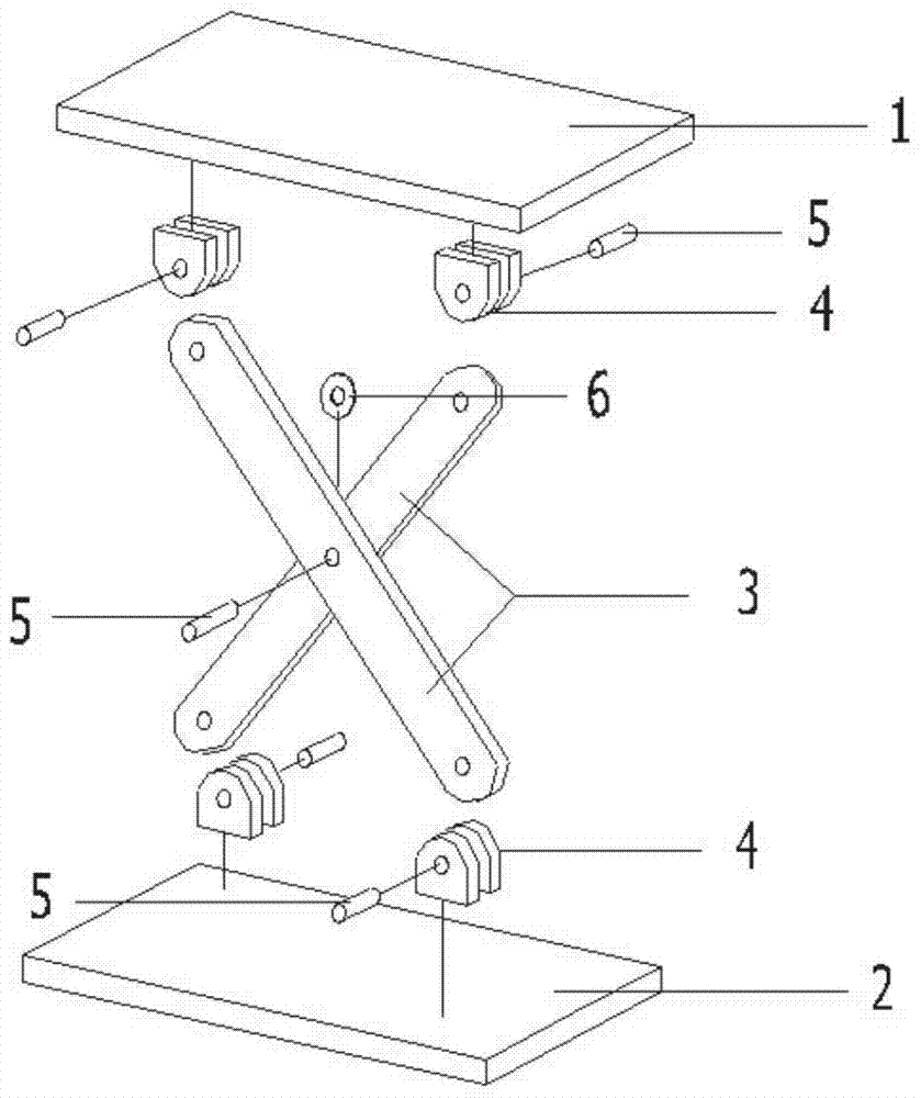
[0021] like image 3 A cross-supported energy dissipator shown includes an upper top plate 1, a lower top plate 2, a set of core energy dissipation components and four lugs 4, and the two lugs 4 are connected to the upper top plate 1 through full penetration welds. On the lower surface, the two lugs 4 are connected to the upper surface of the lower top plate 2 by welding seams. Among them, the energy-consuming components include two core strips 3 and a pin 5, which are made of low-yield point steel below 225MPa or steel with a ductility of 0.45 to 0.5. Both ends and the middle of each core strip 3 locations with through-holes such as Figure 4 As shown, there are several options for the cross-sectional form of the core slats, which can be selected according to their stability requirements. A gasket 6 is arranged between the two core strips 3 , and the surface of the...


PUM


Abstract

The invention discloses a cross-support type energy dissipator, which comprises a core slat, an ear plate, a pin, a spacer and an upper and lower top plate. Each sliding contact position is provided with antifriction material. The core slats are set crosswise, two as a pair. Designers can choose a reasonable logarithm according to their needs. The energy dissipator utilizes the axial deformation of the core slats to dissipate seismic energy. The ear plate mainly plays a fixing role. The pin at the midpoint of the core slats is used to connect the two core slats. When one of the core slats is under compression, the calculated length is reduced by using the pins connected to the tensioned core slats to avoid buckling instability. The energy consumer can be used by adjusting the number of pairs of core slats according to the needs of engineering design.

Description

technical field [0001] The invention relates to a shock absorption device for construction engineering, in particular to a support type energy dissipator. Background technique [0002] Metal energy dissipater is a common type of energy dissipater, which uses metal buckling to absorb seismic energy. Due to its stable performance, low cost and convenient processing, it has been widely used at home and abroad in recent years. [0003] At present, the widely used metal energy dissipators mainly include tension-compression, bending and shearing energy dissipators. Among them, the shear-type energy dissipator has high rigidity and is easy to control the lateral movement, but it is prone to out-of-plane bulging, resulting in hysteretic loop pinching, which cannot achieve full cross-section yielding, and there is obvious stress concentration at the corners, which is easy to appear in advance. Cracks greatly weaken the fatigue life of the energy dissipator and affect the normal oper...

Claims


Application Information

Patent Timeline
Patent Type & Authority Patents(China)
IPC IPC(8): E04B1/98
Inventor 黄镇吴鹏覃作伟
Owner SOUTHEAST UNIV
Why Eureka
Eureka Blog
Learn More