
Automobile power assembly suspension structure

An automobile powertrain and powertrain technology, applied in the direction of power units, vehicle components, jet propulsion devices, etc., can solve problems such as damage to the suspension structure, poor cushioning effect, poor powertrain limit effect, etc., to achieve Guaranteed connection stiffness, good shock absorption effect, and reliable transmission effect

Active Publication Date: 2015-03-25
ZHEJIANG GEELY AUTOMOBILE RES INST CO LTD +1
View PDF13 Cites 2 Cited by
  • Summary
  • Abstract
  • Description
  • Claims
  • Application Information

AI Technical Summary

Problems solved by technology

[0004] Through the analysis of the suspension structure as described in the above patent, the disadvantages of the suspension structure are found: 1. The temperature in the engine compartment is high, the environment of the suspension structure is relatively harsh, and the rubber parts are easy to heat and harden, thus failing , leading to poor shock absorption effect, weak fixation of the powertrain, shaking, etc.; 2. Due to the installation of rubber buffers, the connection stiffness between the powertrain and the subframe 3. Setting a buffer of a single material will easily lead to resonance between the powertrain and the sub-frame assembly, thereby causing damage to the suspension structure or even failure; 4. Poor buffering effect will also cause The noise generated between the powertrain and the sub-frame assembly is relatively large, which affects the comfort of the vehicle

Method used


Image

  • Automobile power assembly suspension structure
  • Automobile power assembly suspension structure
  • Automobile power assembly suspension structure

Examples


Embodiment 1

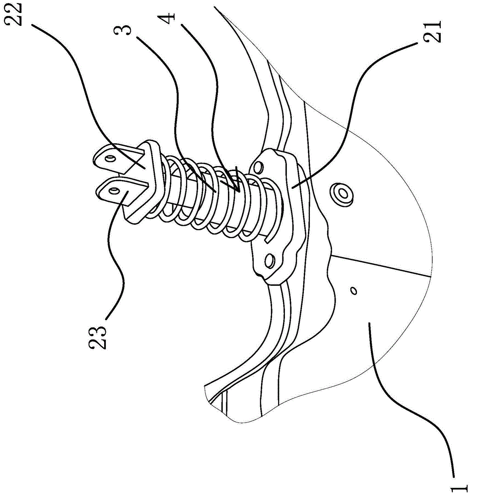
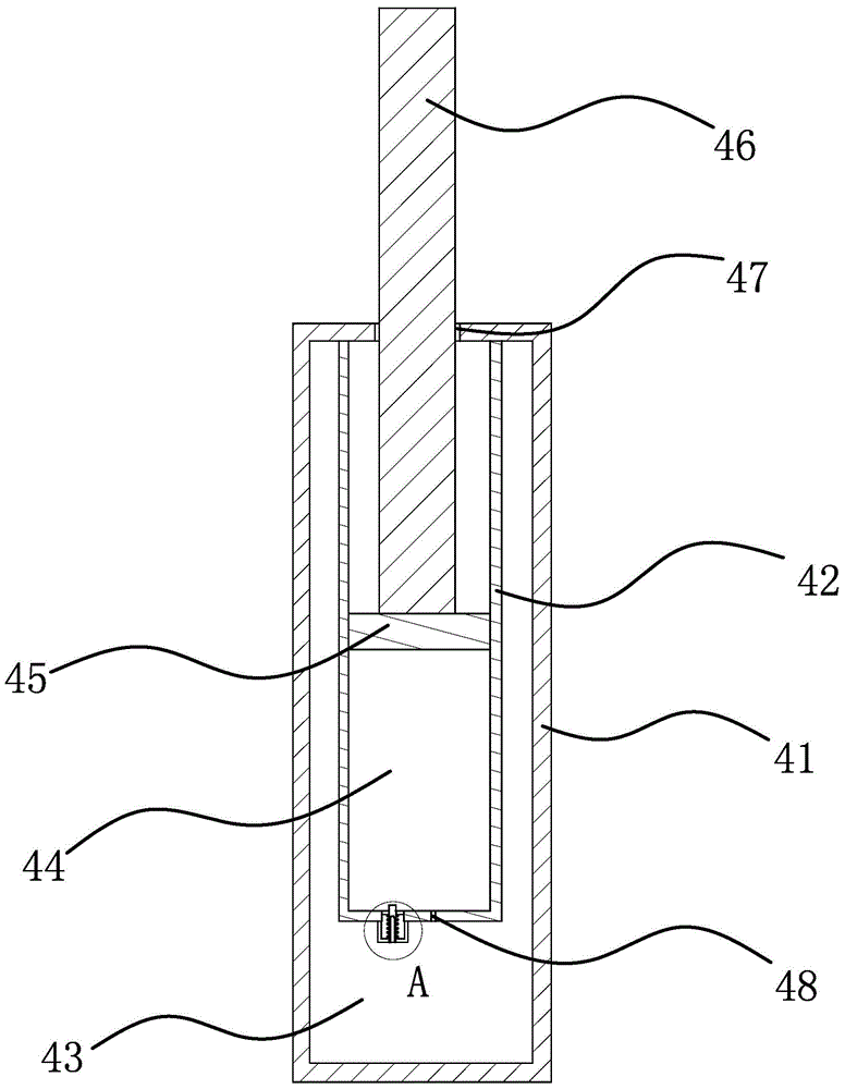
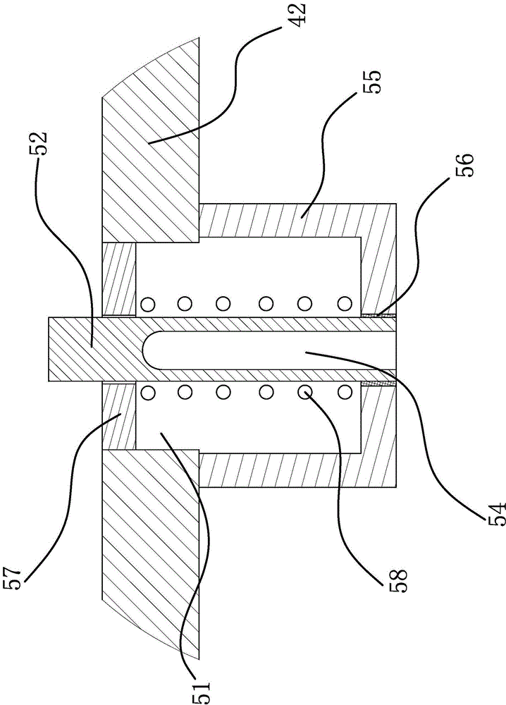
[0023] Such as figure 1 As shown, an automobile powertrain suspension structure. The automobile includes a powertrain and a subframe assembly 1. The suspension structure includes a mounting support 21 fixedly connected to the subframe assembly 1 and a powertrain assembly There is also a spiral damping spring 3 between the two fixed mounting supports 22, the one 21 and the two 22 mounting supports, and the suspension structure also includes a fixed connection to the one 21 and mounting The limiting member 4 between the two supports 22 is placed in the spiral through hole of the shock-absorbing spring 3 and only allows the power assembly to move along the axis of the shock-absorbing spring 3. A plurality of the above-mentioned suspension structures support the power assembly at multiple points, and a spiral damping spring 3 is used to connect between the mounting support 21 and the mounting support 22, in the spiral through hole of the damping spring 3. A limit piece 4 is provide...

Embodiment 2

[0027] The content of this embodiment is roughly the same as that of the first embodiment. The difference is: the cavity one 43 and the cavity two 44 are filled with hydraulic oil. The principle of this solution is the same as that of the above solution. The advantage in comparison is that The hydraulic oil fills the first cavity 43 and the second cavity 44, which makes it easier to seal the piston 45 and the cylinder 42.


PUM


Abstract

The invention provides an automobile power assembly suspension structure and belongs to the technical field of automobiles. The technical problem that an existing power assembly suspension structure can not consider the damping effect and the limiting effect of a power assembly is solved by the automobile power assembly suspension structure. According to the automobile power assembly suspension structure, an automobile comprises a power assembly and an auxiliary frame assembly; the suspension structure comprises a first installation support fixedly connected with the auxiliary frame assembly and a second installation support fixedly connected with the power assembly. A spiral damping spring is arranged between the first installation support and the second installation support. The suspension structure further comprises a limiting piece fixedly connected between the first installation support and the second installation support and arranged in a spiral through hole of the damping spring, so that the power assembly is only allowed to move in the axis direction of the damping spring. The automobile power assembly suspension structure has the advantages that the damping effect is good, the limiting effect between the power assembly and the auxiliary frame assembly is good, and service life is long.

Description

Technical field [0001] The invention belongs to the technical field of automobiles, and relates to an automobile powertrain suspension structure. Background technique [0002] The automobile powertrain suspension system is an important component for multi-point support and limitation of the powertrain. In addition to the basic functions of support and limitation, the suspension system should isolate the powertrain, reduce noise, and eliminate Resonance and other functions to improve the NVH performance of the car. [0003] The suspension system connects the powertrain with the subframe assembly through multiple suspension structures. In the prior art, almost all automobile powertrain suspension systems are realized by using multiple anti-torsion rods. For example, a Chinese patent [CN 202937721U] discloses a new type of anti-torsion rod, which aims to overcome the shortcomings of the prior art that the anti-torsion rod has insufficient longitudinal tensile and torsional stability....

Claims


Application Information

Patent Timeline
Patent Type & Authority Applications(China)
IPC IPC(8): B60K5/12
Inventor 孙达刘全有李功赋吴成明冯擎峰
Owner ZHEJIANG GEELY AUTOMOBILE RES INST CO LTD
Learn More