
Roller coder for coding workpieces by using extrusion principle and method of use thereof

A rolling code machine and workpiece technology, which is applied in the field of rolling code machines, can solve problems such as hidden safety hazards, low efficiency, and many defective products, and achieve the effects of high safety, simple operation, convenient and reliable operation

Inactive Publication Date: 2016-08-31
MAANSHAN CITY ZHIFENG MACHINERY
View PDF6 Cites 0 Cited by
  • Summary
  • Abstract
  • Description
  • Claims
  • Application Information

AI Technical Summary

Problems solved by technology

[0005] Aiming at the problems existing in the prior art, such as hidden safety hazards, low efficiency, and many defective products in sensor-type stamping and coding, the present invention provides a rolling code that utilizes the principle of extrusion to code the workpiece. machine and how to use it

Method used


Image

  • Roller coder for coding workpieces by using extrusion principle and method of use thereof
  • Roller coder for coding workpieces by using extrusion principle and method of use thereof
  • Roller coder for coding workpieces by using extrusion principle and method of use thereof

Examples


Embodiment 1

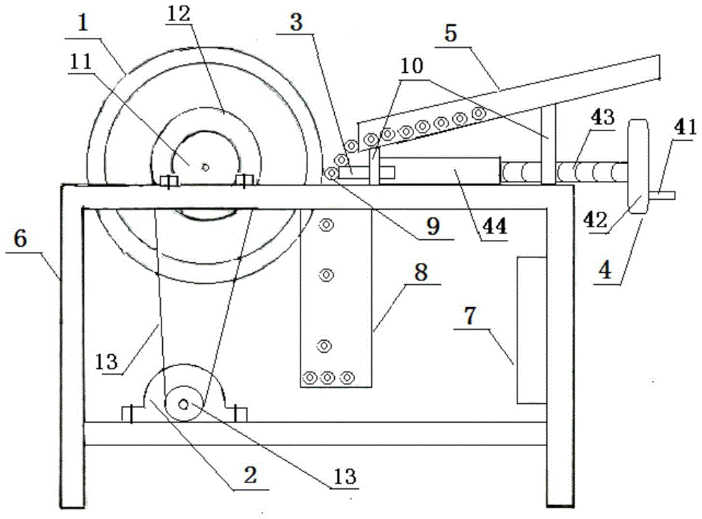
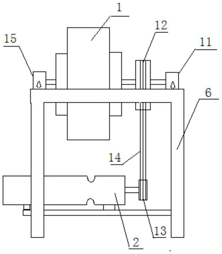
[0035] Such as figure 1 As shown, a rolling code machine of this embodiment that utilizes the principle of extrusion to code workpieces includes a reducer 2, a feed trough 5, a frame-shaped support 6, an electric box 7 and a discharge port 8, and also includes an inertial Flywheel 1, steel code 3 and extrusion adjustment mechanism 4; the front end of the reducer 2 is provided with a lower pulley 13; the front end of the inertial flywheel 1 is provided with an upper pulley 12; the reducer 2 is fixedly installed on The left part of the lower crossbeam of the frame support 6; as figure 2 As shown, the centers of circles of the inertial flywheel 1 and the upper pulley 12 are on the same axis, the two are connected by a rotating shaft, and are fixed in the bearings A11 and B15 respectively arranged on the front and rear two upper beams of the frame support 6, the bearings A11 and bearing B15 are fixed on the front and rear two upper beam upper surfaces of the frame-shaped support...


PUM


Abstract

The invention discloses a code rolling machine conducting code pressing on a workpiece based on an extruding principle and a using method of the code rolling machine and belongs to the technical field of code printing machines. The code rolling machine conducting code pressing on the workpiece based on the extruding principle comprises a reducer, a feeding groove, a frame-shaped support, an electric box and a discharging port and further comprises an inertia flywheel, a steel code and an extruding adjusting mechanism. The circle center of the inertia flywheel and the circle center of an upper belt pulley are located on the same axis, and the inertia flywheel and the upper belt pulley are connected through a rotating shaft and fixed in a bearing A and a bearing B which are arranged on a front beam and a rear beam of the frame-shaped support respectively. A lower belt pulley and the upper belt pulley are in transmission connection through a belt. A discharging port of the feeding groove is right opposite to the peripheral face of the inertia flywheel, an embossed steel code is arranged on the left end face of the steel code, and an extrusion opening is formed between the left end face of the steel code and the peripheral face of the inertia flywheel. The using method of the code rolling machine conducting code pressing on the workpiece based on the extruding principle is simple in operation, high in automation degree and production efficiency, clear in code printing and high in operation safety.

Description

technical field [0001] The invention belongs to the mechanical technical field of coding machines, and more specifically relates to a rolling coding machine for coding workpieces by using the principle of extrusion and a method for using the same. Background technique [0002] At present, the conventional threaded sleeve steel bar coding machine must be manually fed individually and stamped with a vertical punch. An arm injury occurred. [0003] Chinese Patent Publication No.: 202225560U, Publication Date: May 23, 2012, discloses a coding machine capable of automatic printing. The utility model includes a printer head, a control box, a body and a base. device, the bottom end of the stamping device is provided with a steel die, one end of the printer head is provided with a rotating shaft, the rotating shaft is installed on the rotating shaft of the motor, and an electric transmission crawler is arranged on the base, and the electric transmission crawler is located on the ba...

Claims


Application Information

Patent Timeline
Patent Type & Authority Patents(China)
IPC IPC(8): B41K3/36B41K3/44B41K3/62
Inventor 王广流
Owner MAANSHAN CITY ZHIFENG MACHINERY
Learn More