
Novel welding equipment

A welding equipment, a new type of technology, applied in the direction of welding equipment, welding equipment, auxiliary welding equipment, etc., can solve the problems of heavy equipment workload, low stability, high energy consumption, etc., to improve welding stability, increase adjustment methods, The effect of expanding the scope of application

Inactive Publication Date: 2015-03-25
天津市德通制罐有限公司
View PDF0 Cites 2 Cited by
  • Summary
  • Abstract
  • Description
  • Claims
  • Application Information

AI Technical Summary

Problems solved by technology

[0003] 1. Since the surface height of the rotating tank will change, the beam on the top of the frame is lifted up and down to adjust the welding torch assembly up and down. The equipment has a large workload and consumes a lot of energy. Moreover, the stability and quality of welding are low. Difference
[0004] 2. The welding equipment can only be welded by pushing the can body to the predetermined position, and the size of the predetermined position is set according to the actual needs of the production line, and can only meet the corresponding size of the tank body, so the range of applicable tank types is relatively large. Small

Method used


Image

  • Novel welding equipment

Examples


Embodiment

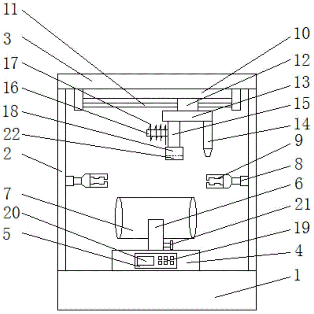
[0021] Such as figure 1 As shown, this embodiment includes an operating table 1, a column 2, a top plate 3, a lifting platform 4, an operating area 5, a clamping groove 6, a tank body 7, a telescopic rod 8, a clamp 9, an electric cylinder 10, a guide rail 11, an electric slide Block 12, connecting plate 13, welding torch 14, connecting rod 15, rotating shaft 16, welding wire 17 and briquetting block 18, the four corners of console 1 are respectively fixed with column 2 lower ends, and column 2 upper ends are fixed on top plate 3 corresponding positions, The middle part of the console 1 is equipped with a lifting platform 4, and the front side of the lifting platform 4 is provided with an operation area 5. The operating area 5 includes a keyboard 19 and a display screen 20. The lifting platform 4 on the upper side of the keyboard 19 is provided with a display screen 20, and the lifting platform 4 The middle part of the upper side is fixed with a clamping groove 6, and the right...


PUM


Abstract

The invention belongs to the technical field of welding equipment and particularly relates to novel welding equipment. The novel welding equipment comprises an operation table, stand columns, a top plate, a lifting platform, an operation region, a clamping groove, a tank, telescopic rods, fixtures, an electric cylinder, a guide rail, an electric sliding block, a connecting plate, a welding gun, a connecting rod, a rotary shaft, a welding wire and a pressing block. The lower ends of the stand columns are fixed to the four corners of the operation table respectively. The upper ends of the stand columns are fixed to corresponding positions of the top plate. The lifting platform is mounted in the middle of the operation table. The front side of the lifting platform is provided with the operation region. The clamping groove is fixed to the middle of the upper side of the lifting platform. The tank is placed in the clamping groove. The telescopic rods are correspondingly mounted on the stand columns on the two sides of the tank. The fixtures are fixed to the telescopic rods. The electric cylinder is fixed to the lower side of the top plate. The electric sliding block is mounted on the guide rail of the electric cylinder. The novel welding equipment is high in welding stability and wide in application range.

Description

technical field [0001] The invention belongs to the technical field of welding equipment, and in particular relates to a novel welding equipment. Background technique [0002] At present, in the production process of the tank body, the welding equipment needs to weld the tank body to seal it. In the welding process of the welding equipment in the prior art, the metal sheet is first cut into neat metal sheets according to the specifications, and then the metal sheet is bent into a circle. Cylindrical can body, the cylindrical can body is transported to the predetermined position by the circular motion conveyor belt, and then the can body is pushed by the canning device, and the can body is pushed into the upper and lower welding wheels without misalignment, and then , and then seal and weld the lap seams of the can body through high-frequency resistance. However, the welding equipment of this structure has the following problems in actual use: [0003] 1. Since the height o...

Claims


Application Information

Patent Timeline
Patent Type & Authority Applications(China)
IPC IPC(8): B23K9/32B23K9/12
CPCB23K9/00B23K9/12B23K9/32B23K37/0435B23K2101/125
Inventor 芦东利
Owner 天津市德通制罐有限公司
Learn More