
Reverse power over Ethernet system and method, and load sharing device and powered device

A technology of load sharing and power receiving equipment, applied in the direction of data switching current source, data exchange details, etc., can solve the problems of system instability, power consumption, and different arrival voltage, so as to improve system stability and avoid switching back and forth Effect

Active Publication Date: 2015-03-18
CHINA TELECOM CORP LTD
View PDF3 Cites 8 Cited by
  • Summary
  • Abstract
  • Description
  • Claims
  • Application Information

AI Technical Summary

Problems solved by technology

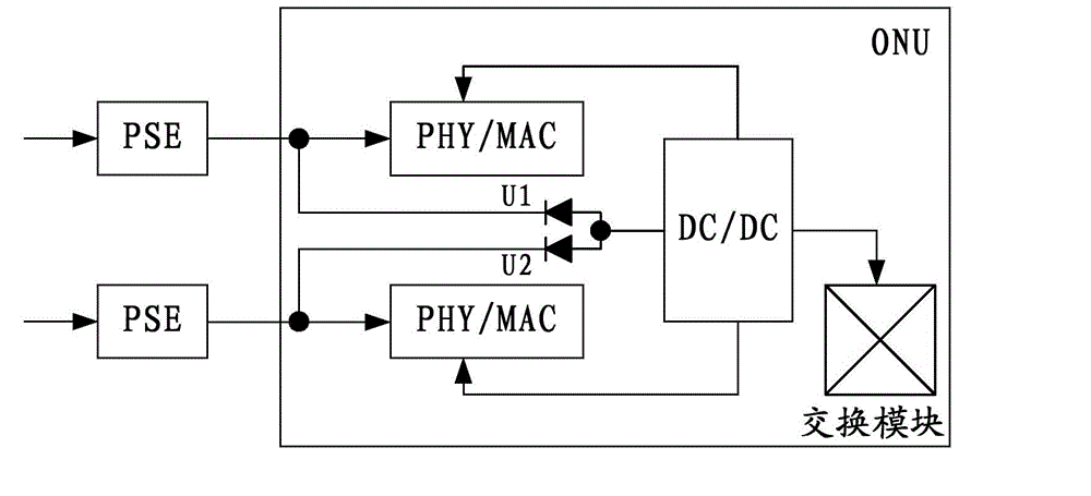
Due to the difference in the length of the five types of cables, the line resistance is different, resulting in different arrival voltages at ports U1 and U2.
According to the conduction characteristics of the diode, the high-voltage line supplies power to the system, and other lines do not bear the power of the system. There are two problems in this way: on the one hand, it is not fair for high-voltage users to supply power alone; on the other hand, high-voltage users After the line is connected, the online high-voltage user power supply is automatically reselected, causing the system power supply to switch back and forth between different lines, which may easily cause system instability or failure
[0005] In addition, in the above system, as long as a user supplies power to the equipment normally, whether other line users are online or not, the line is always in the normal power supply state, and the power consumption

Method used


Image

  • Reverse power over Ethernet system and method, and load sharing device and powered device
  • Reverse power over Ethernet system and method, and load sharing device and powered device
  • Reverse power over Ethernet system and method, and load sharing device and powered device

Examples


Embodiment Construction

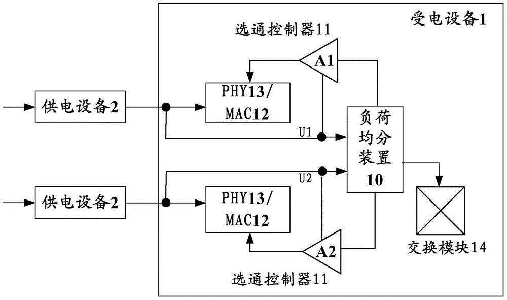
[0026] The following will clearly and completely describe the technical solutions in the embodiments of the present invention with reference to the accompanying drawings in the embodiments of the present invention. Obviously, the described embodiments are only some, not all, embodiments of the present invention. The following description of at least one exemplary embodiment is merely illustrative in nature and in no way taken as limiting the invention, its application or uses. Based on the embodiments of the present invention, all other embodiments obtained by persons of ordinary skill in the art without creative efforts fall within the protection scope of the present invention.

[0027] In the reverse power over Ethernet technology, in order to solve the unfair problem of being powered by high-voltage users alone, and the switching of power supply ports caused by the change of the voltage extracted from each line when the user goes online and offline, the present invention pro...


PUM


Abstract

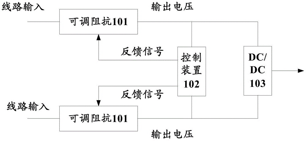
The invention discloses a reverse power over Ethernet (POE) system and method, and a load sharing device and a powered device and relates to the field of POE. The reverse POE system includes the powered device and a plurality of power supplying devices. Each power supplying device is connected with the powered device. The powered device includes the load sharing device. The load sharing device includes a plurality of controllable impedors, a control device and a DC-to-DC converter. A power signal of each power supplying device is output to the DC-to-DC converter through an adjustable impedor. The control device carries out sampling on voltages output by the adjustable impedors. If a condition that the output voltages of the adjustable impedors are imbalanced happens, feedback signals are output to the adjustable impedors so as to readjust impedances to enable the output voltages of the adjustable impedors to be balanced. The DC-to-DC converter carries out DC conversion on balance voltages output by the adjustable impedors so as to provide the voltage to the powered device and thus power supplying load sharing is realized and switching back and forth of power supplying ports is prevented and system stability is improved.

Description

technical field [0001] The present invention relates to the field of Power Over Ethernet (POE for short), in particular to a reverse Ethernet power supply system and method, a load sharing device and a power receiving device. Background technique [0002] During the construction of FTTx (optical fiber access) network, some communities or buildings have power supply difficulties. Using reverse power over Ethernet technology can effectively solve the problem of power supply difficulties and promote the smooth progress of FTTx network construction. [0003] Ethernet technology refers to the technology that uses the existing Ethernet five-category (Cat.5) wiring to provide DC power supply while transmitting data signals. Reverse Power over Ethernet technology utilizes the Power Sourcing Equipment (PSE) in the user's home to reversely supply power to the network equipment through the five-category line, so as to solve the power supply problem of the network equipment when the con...

Claims


Application Information

Patent Timeline
Patent Type & Authority Applications(China)
IPC IPC(8): H04L12/10
Inventor 庄湛海兰潮叶何亮余丹高小兵叶玉剑殴振猛朱宜兵
Owner CHINA TELECOM CORP LTD
Learn More