


Quick Research
Generate reliable direction feasibility study reports for your R&D in just a few steps.

Technical Q&A
Discover and master advanced knowledge NOW. Basics, ideas, possibilities, all at once.

Find Solutions
As an expert in R&D theories, this can generate solutions to your technical problems instantly.

Evaluate Feasibility
Analyze your overall solution with one click, know your potential R&D risks in advance.

Monitor Landscape
Get weekly tech updates, stay abreast of the latest tech innovations and key insights.
Driving cylinder
A technology of active cylinders and brakes, applied in brake actuators, fluid-driven clutches, non-mechanical drive clutches, etc., can solve problems such as leakage
- Summary
- Abstract
- Description
- Claims
- Application Information
AI Technical Summary
Problems solved by technology
Method used
Image

Examples
Embodiment Construction
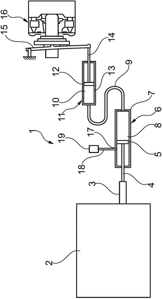
[0027] figure 1 A pressure medium actuating device 1 is shown which has an actuating actuator 2 with an output element 3 which is connected via a connecting rod 4 to a piston 5 of a master cylinder 6 . The piston 5 is arranged axially displaceable in the cylinder 7 of the master cylinder 6 so that the volume of the working pressure chamber or pressure chamber 8 can be varied so that a fluid, in this case a pressure medium, can be acted upon from The pressure chamber 8 enters via a connecting line 9 into a second pressure chamber 10 of another piston-cylinder unit, also referred to as a slave cylinder 11 . The piston 12 in the cylinder 13 of the slave cylinder 11 thus moves in the axial direction and can actuate, eg engage or disengage, via the connecting rod 14 and the lever 15 or other connecting elements, for example, the clutch 16 . In alternative embodiments, the element to be actuated can also be a transmission element or the like.
[0028] The master cylinder 6 also has ...
PUM
 Abstract
Description
Claims
Application Information
 - R&D Engineer
- R&D Manager
- IP Professional
- Industry Leading Data Capabilities
- Powerful AI technology
- Patent DNA Extraction
Browse by: Latest US Patents, China's latest patents, Technical Efficacy Thesaurus, Application Domain, Technology Topic, Popular Technical Reports.
© 2024 PatSnap. All rights reserved.Legal|Privacy policy|Modern Slavery Act Transparency Statement|Sitemap|About US| Contact US: help@patsnap.com