
Method for replacing a machine tool and a tool

A tool replacement and tool technology, applied in the direction of manufacturing tools, metal processing equipment, metal processing machinery parts, etc., can solve problems such as the deviation of the main shaft from the origin position

Active Publication Date: 2015-03-18
BROTHER KOGYO KK
View PDF5 Cites 2 Cited by
  • Summary
  • Abstract
  • Description
  • Claims
  • Application Information

AI Technical Summary

Problems solved by technology

Therefore, there is a problem that the position of the main axis will greatly deviate from the position of the origin

Method used


Image

  • Method for replacing a machine tool and a tool
  • Method for replacing a machine tool and a tool
  • Method for replacing a machine tool and a tool

Examples


Deformed example 1

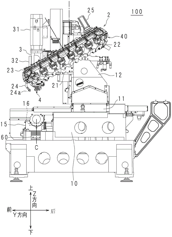
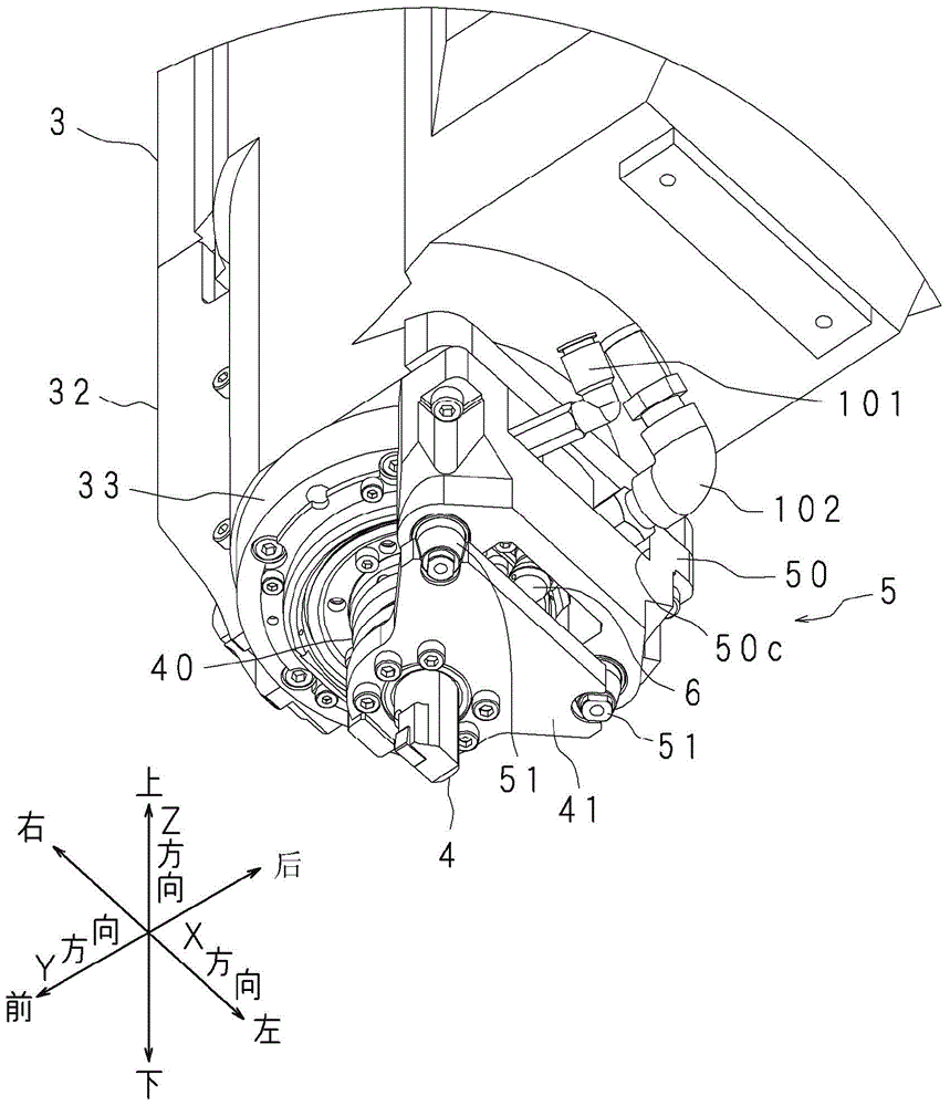
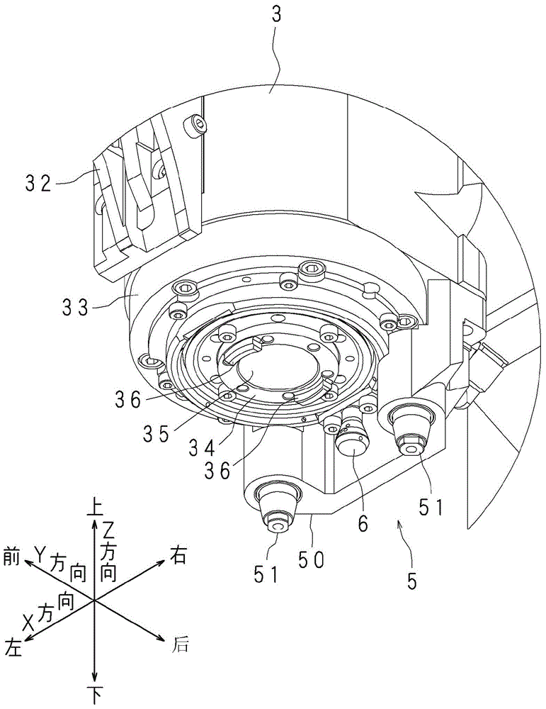
[0087] In the machine tool 100 of Modification 1, at least until the tool 4 is detached from the spindle 34 for tool replacement, the control method of the spindle motor 31 is changed from the rotation control based on the differential value and the cumulative value to the control method based on the differential value without using the cumulative value. Rotation control toggle by value. When the tool 4 is detached from the spindle 34, the machine tool 100 does not perform rotation control based on the accumulated value. Therefore, when the turning tool (non-rotating tool) is removed for replacement, it is possible to prevent the spindle 34 from rotating to a position largely deviated from the origin position due to the accumulation of errors of the spindle 34 relative to the origin position.

Deformed example 2

[0089] The machine tool 100 of Modification 2 determines whether the tool 4 attached to the spindle 34 is a rotary tool or a turning tool (non-rotary tool). The machine tool 100 switches the rotation control method of the spindle motor 31 according to the determination result. The machine tool 100 stores, for example, a machining program describing workpiece machining conditions, machining details, machining commands, etc., in the storage unit 81 c of the control device 80 . The control unit 81 of the control device 80 processes the workpiece by controlling the X-axis drive control unit 82 to the C-axis drive control unit 87 and the like based on the machining program stored in the storage unit 81c. The machine tool 100 determines whether the tool attached to the spindle 34 is a rotary tool or a turning tool based on the contents of the machining program or the like.

[0090] The control unit 81 of the control device 80 sequentially reads commands from the first line of the m...


PUM


Abstract

The invention relates to a method for replacing a machine tool and a tool and for replacing a tool stored in a storage part and a tool for mounting a spindle. A machine tool calculates a difference value between a target position around the axis and a current position of the spindle, and calculates a cumulative value of the calculated difference value. A switching part switches between the rotational control of a spindle motor based on the difference value and the cumulative value and the rotational control of the spindle motor based on the difference value without the use of the cumulative value. From a machining position to a switching position, the switching part of the machine tool performs the rotational control of the spindle motor based on the difference value and the cumulative value, and from the switching position to a replacing position, the switching part of the machine tool performs the rotational control based on the difference value. Even if the replacement of a tool is carried out when a non-rotational tool is mounted to the spindle, the machine tool can also avoid excessive load acting onto a motor and like enabling the rotation of the spindle.

Description

technical field [0001] The present invention relates to a machine tool and a tool replacement method for replacing a tool stored in a storage unit with a tool attached to a spindle. Background technique [0002] Machine tools include spindles, supports and tool magazines. The spindle is used to mount the tool. The supporting part supports the workpiece and can rotate around the vertical axis. The tool magazine stores the tools attached to the spindle. Tools include rotary tools and non-rotary tools. The rotary tool rotates together with the spindle. Non-rotating tools are fixed to the spindle head that supports the spindle and therefore do not rotate. When the rotary tool is attached to the spindle, the workpiece does not rotate around the vertical axis. The machine tool processes the workpiece by fixing the workpiece to the support and rotating the spindle. When a non-rotating tool is attached to the main shaft, the workpiece rotates around the vertical axis together...

Claims


Application Information

Patent Timeline
Patent Type & Authority Applications(China)
IPC IPC(8): B23Q3/155
CPCB23Q3/1556
Inventor 寺田弦
Owner BROTHER KOGYO KK
Learn More