
Zoom lens and imaging device

一种变焦透镜、透镜群的技术,应用在放映装置、洗印装置、图像通信等方向,能够解决无法充分满足高变倍比和广角化的要求、不能达成广角化等问题,达到广角化低成本化、廉价构成、高变倍比的效果

Inactive Publication Date: 2015-03-11
FUJIFILM CORP
View PDF3 Cites 8 Cited by
  • Summary
  • Abstract
  • Description
  • Claims
  • Application Information

AI Technical Summary

Problems solved by technology

[0009] However, the zoom lens described in Patent Document 1 has a zoom ratio of about 11 to 12, which cannot fully meet the recent demands for high zoom ratios and wide angles.
The zoom lens described in Patent Document 2 has a zoom ratio of about 20, which can be called a high zoom ratio, but it cannot achieve wide-angle.
Although the zoom lens described in Patent Document 3 has a high zoom ratio of about 20, it cannot achieve wide-angle

Method used


Image

  • Zoom lens and imaging device
  • Zoom lens and imaging device
  • Zoom lens and imaging device

Examples


Embodiment 1

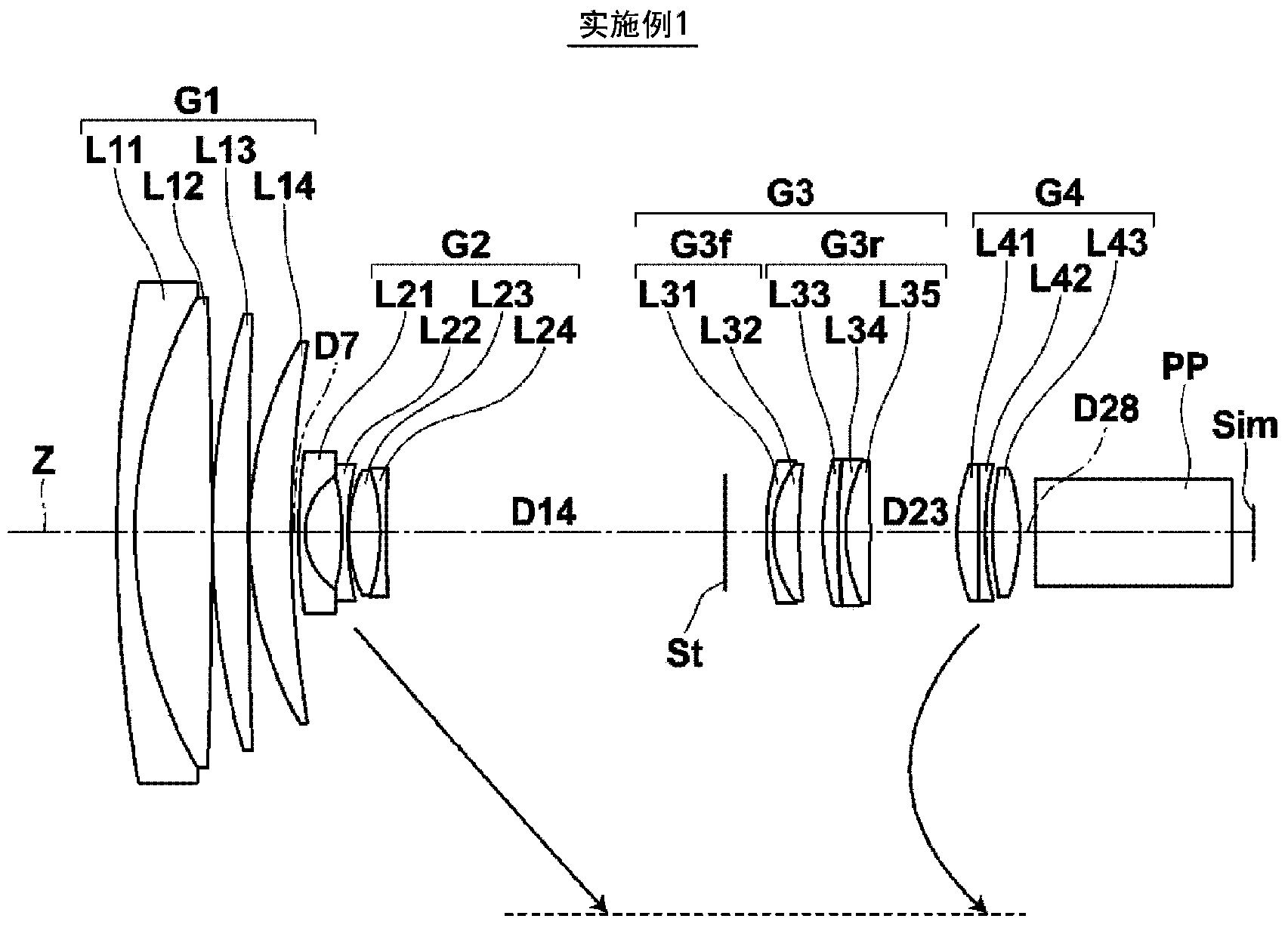
[0139] The basic lens data of the zoom lens of Example 1 are shown in Table 1, the other data are shown in Table 2, and the aspheric coefficients are shown in Table 3. Similarly, basic lens data, other data, and aspheric coefficients of the zoom lenses of Examples 2 to 11 are shown in Tables 4 to 33. Hereinafter, the meanings of the symbols in the tables will be described taking Example 1 as an example, and the meanings of Examples 2 to 11 are basically the same. Note that each numerical data shown in Tables 1 to 33 is normalized so that the focal length at the wide-angle end is 1. FIG.

[0140] In the basic lens data in Table 1, the column of Si indicates the i-th number (i=1, 2, 3....) surface number, the Ri column indicates the radius of curvature of the i-th surface, and the Di column indicates the surface interval on the optical axis Z of the i-th surface and the i+1-th surface. In addition, the sign of the radius of curvature is positive when the surface shape is conve...

Embodiment 2

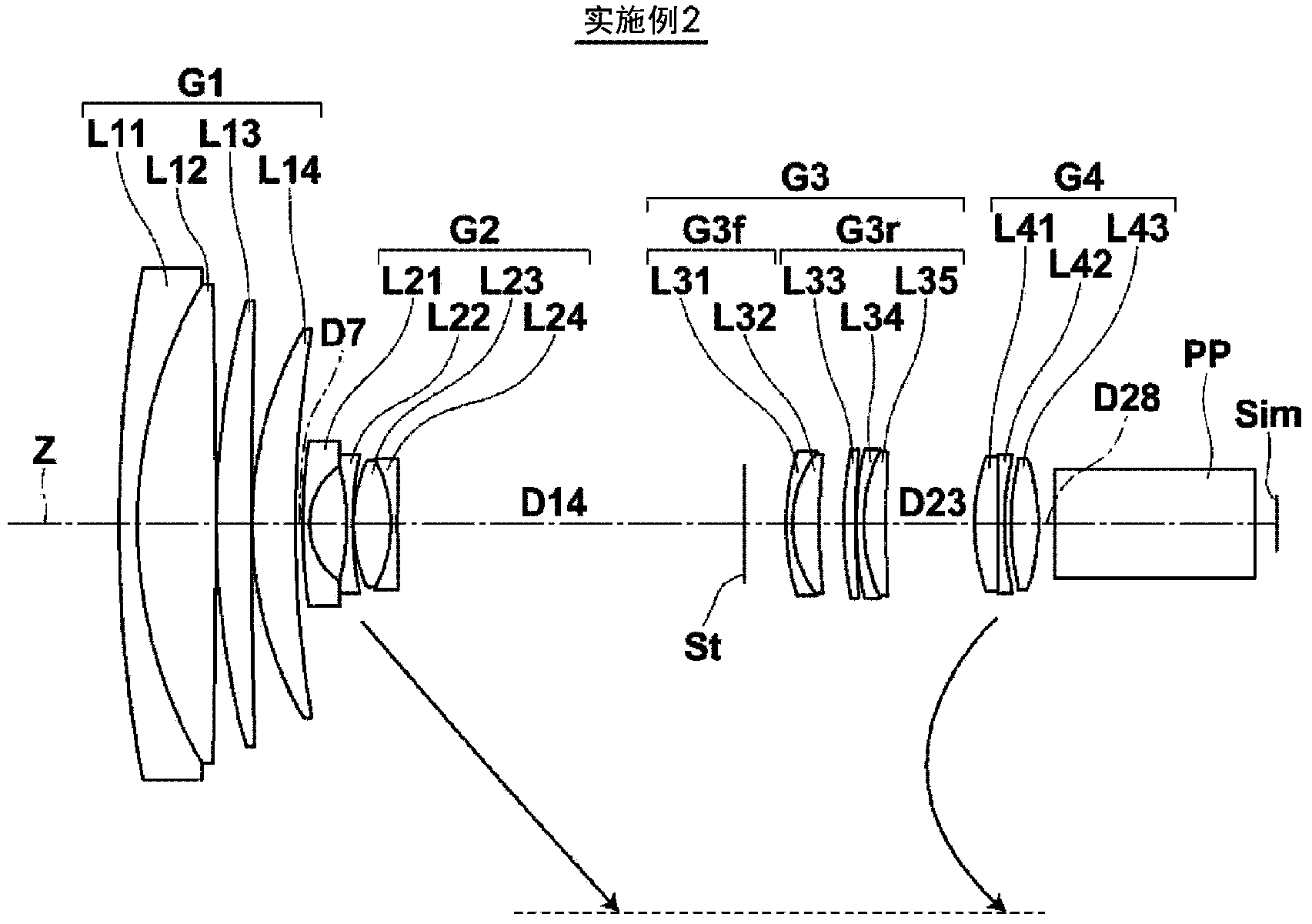
[0164] Example 2 Lens data

[0165] Si

[0166] 【table 5】

[0167] Example 2. Other data

[0168]

[0169] 【Table 6】

[0170] Embodiment 2. Aspheric coefficient

[0171] face number

[0172] 【Table 7】

Embodiment 3

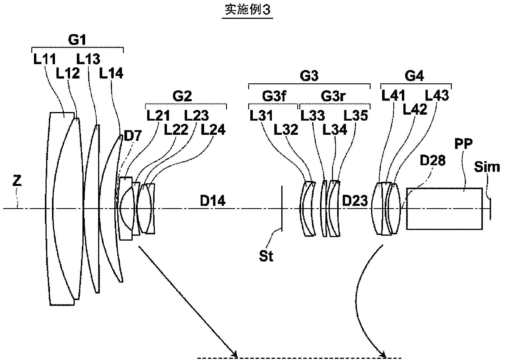
[0173] Example 3 Lens Data

[0174] Si

[0175] 【Table 8】

[0176] Example 3. Other data

[0177]

[0178] 【Table 9】

[0179] Embodiment 3. Aspheric coefficient

[0180] face number

[0181] 【Table 10】


PUM


Abstract

[Problem] To achieve higher performance, higher magnification, wider angle, lower cost and the acquisition of more favorable images for a zoom lens. [Solution] A zoom lens comprises, in order from an object side, a positive first lens group (G1), a negative second lens group (G2), a positive third lens group (G3) and a positive fourth lens group (G4). When zooming from a wide-angle end to a telephoto end, the first lens group (G1) and the third lens group (G3) are fixed in the optical axis direction, the second lens group (G2) moves toward the image side, and the fourth lens group (G4) moves in the optical axis direction. The second lens group (G2) includes an air gap between mutually facing convex and concave surfaces and a joint surface between negative and positive lenses. The third lens group (G3) comprises a fixed front group (G3f) and a rear group (G3r) in order from the object side, the rear group (G3r) having a positive refractive power and allowing for the shift of a reduction-side image by shifting in a direction intersecting with the optical axis.

Description

technical field [0001] The present invention relates to a zoom lens and an imaging device, and particularly relates to a zoom lens applicable to video cameras, broadcast cameras, surveillance cameras, etc., and an imaging device equipped with the zoom lens. Background technique [0002] Conventionally, as zoom lenses that can be used in the above-mentioned fields, there are four known zoom lenses in which a positive first lens group, a negative second lens group, a positive third lens group, and a positive fourth lens group are arranged in order from the object side. Group-structured lens systems. For example, in the following patent documents 1 to 3, there is described a kind of rear focus type lens system, which is a zoom lens with the above-mentioned 4-group structure, and when changing magnification from the wide-angle end to the telephoto end, the first lens group and the third lens group The lens group is fixed, the second lens group and the fourth lens group move, an...

Claims


Application Information

Patent Timeline
Patent Type & Authority Applications(China)
IPC IPC(8): G02B15/16G02B13/18G03B5/00H04N5/225
CPCG02B15/16G03B5/00G02B15/173G02B13/18G02B15/144113G02B27/646
Inventor 川名正直
Owner FUJIFILM CORP
Learn More