
Axial foil-free diode composite guiding magnetic field system

A foil-free diode and guided magnetic field technology, which is applied in discharge tubes, transit-time electronic tubes, electrical components, etc., can solve the problem of volume, weight, and energy consumption of solenoids and auxiliary power equipment, which are unfavorable for mobile platform applications, insulators, etc. Insulation damage and other problems, to achieve the effect of small coil weight and power supply, compact system structure, and enhanced magnetic field strength

Active Publication Date: 2015-03-11
INST OF APPLIED ELECTRONICS CHINA ACAD OF ENG PHYSICS
View PDF3 Cites 2 Cited by
  • Summary
  • Abstract
  • Description
  • Claims
  • Application Information

AI Technical Summary

Problems solved by technology

But this will inevitably lead to a waste of the magnetic field at the end of the solenoid, and a small amount of backflow electrons will move in the opposite direction along the magnetic field lines at the end, and it is easy to bombard the insulator and cause insulation damage or bombard the anode cylinder to cause electron energy loss.
In addition, in order to meet the withstand voltage requirements, a large distance needs to be maintained between the inner wall of the solenoid and the cathode rod, resulting in a large volume, weight, and energy consumption of the solenoid and its auxiliary power equipment, which is not conducive to the application of mobile platforms

Method used


Image

  • Axial foil-free diode composite guiding magnetic field system
  • Axial foil-free diode composite guiding magnetic field system

Examples


Embodiment Construction

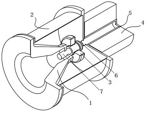
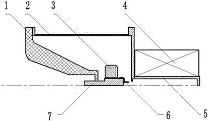
[0024] Such as figure 1 , figure 2 As shown, the axial foil-free diode in the present invention includes a ring-shaped cathode made of a circular conductor with a certain thickness, an insulator made of nylon or other insulating materials, an anode cylinder made of a conductor outside, and a drift made of a conductor. Tube. The composite guiding magnetic field system includes a soft magnet made of A3 steel or other soft magnetic materials connected to the back end of the ring cathode, a permanent magnet ring made of permanent magnet materials coaxially installed outside the soft magnet, and a A solenoid mounted on the outside of the drift tube. In the present invention, the annular cathode is located in the gap area between the permanent magnet ring and the solenoid, and the permanent magnet ring adopts radial magnetization, and the magnetic field formed by the permanent magnet ring is superimposed on the magnetic field at the end of the solenoid, so that the annular The m...


PUM


Abstract

The invention discloses an axial foil-free diode composite guiding magnetic field system, which comprises an insulator, an anode cylinder, an annular cathode, a drift tube, a solenoid, a magnet column and a permanent magnet ring, wherein the solenoid, the magnet column and the permanent magnet ring are installed at the outer side of the drift tube in an enclosing mode; one side of the drift tube is provided with the annular cathode, and the other side of the annular cathode is connected with one end of the magnet column; and the other end of the magnet column penetrates through the permanent magnet ring and the insulator and is connected with the external part. According to the invention, stable and efficient transmission for electron beams in the axial direction is realized through using the permanent magnet ring, the solenoid and the soft magnet in a combination mode. In addition, the system disclosed by the invention is compact in structure, light in weight and low in power required to be consumed, and the generated magnetic field distribution can be adjusted conveniently.

Description

technical field [0001] The invention relates to the field of magnetic field guidance, in particular to an axial non-foil diode composite guiding magnetic field system formed by a combination of a permanent magnet ring, a solenoid and a soft magnet. Background technique [0002] In the process of practical development of high power microwave source system, the high efficiency and miniaturization of the system is a crucial factor. In order to achieve this goal, in addition to striving to improve the design level of microwave devices to improve their work efficiency, optimization and improvement of systems such as electron beam sources and guiding magnetic fields are also important directions. Axial foil-free diodes are commonly used in high-power microwave sources, and their guiding magnetic field systems mainly include solenoids, superconducting magnetic fields, and permanent magnetic rings. Among them, the superconducting magnetic field system has high manufacturing and ope...

Claims


Application Information

Patent Timeline
IPC IPC(8): H01J23/087
CPCH01J23/087
Inventor 李春霞于爱民吴洋王淦平邓德荣李文君马乔生许州金晓杨晓亮张北镇
Owner INST OF APPLIED ELECTRONICS CHINA ACAD OF ENG PHYSICS
Learn More