
Underwater charging station

A recharging and battery technology, applied in underwater ships, underwater operation equipment, exchange data chargers, etc., can solve problems such as loss

Inactive Publication Date: 2015-03-04
艺格比奇技术公司
View PDF5 Cites 10 Cited by
  • Summary
  • Abstract
  • Description
  • Claims
  • Application Information

AI Technical Summary

Problems solved by technology

Although rechargeable batteries have the ability to be recharged, these batteries lose their ability to hold the same original charge as the battery ages and / or is used

Method used


Image

  • Underwater charging station
  • Underwater charging station
  • Underwater charging station

Examples


Embodiment Construction

[0044] Exemplary embodiments provide apparatus and methods for using reserve batteries to provide backup or supplemental power, for example, for subsea applications. The present invention is applicable to a variety of subsea applications including, for example, point-of-load power distribution, hybrid power systems, and any critical system backup such as for powering emergency blowout preventers (or for providing backup power thereto). Accordingly, while embodiments are described for use in subsea applications, the described embodiments are exemplary only. Other embodiments are applicable to various emergency situations, long-term storage situations, and situations requiring battery / battery reliability.

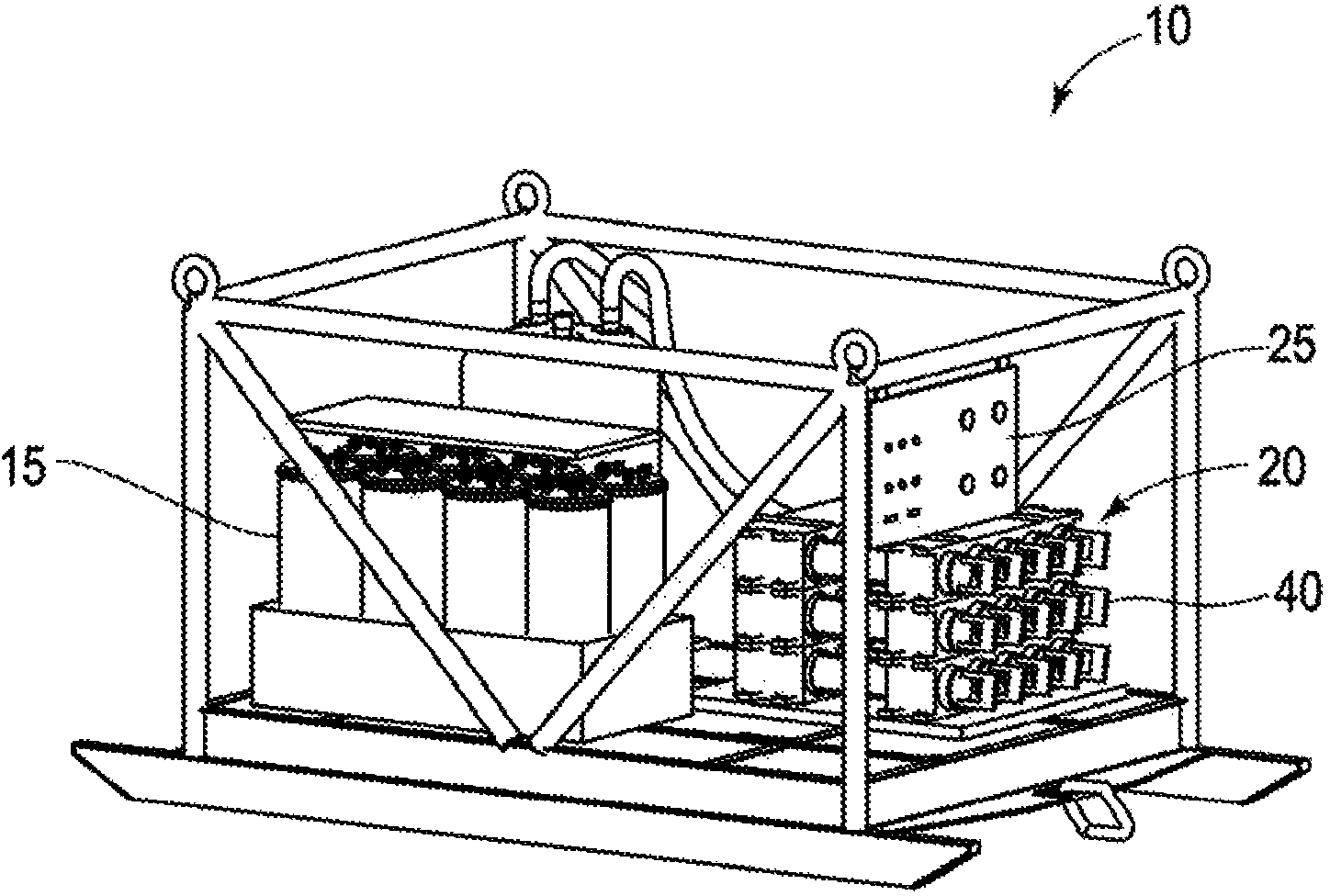
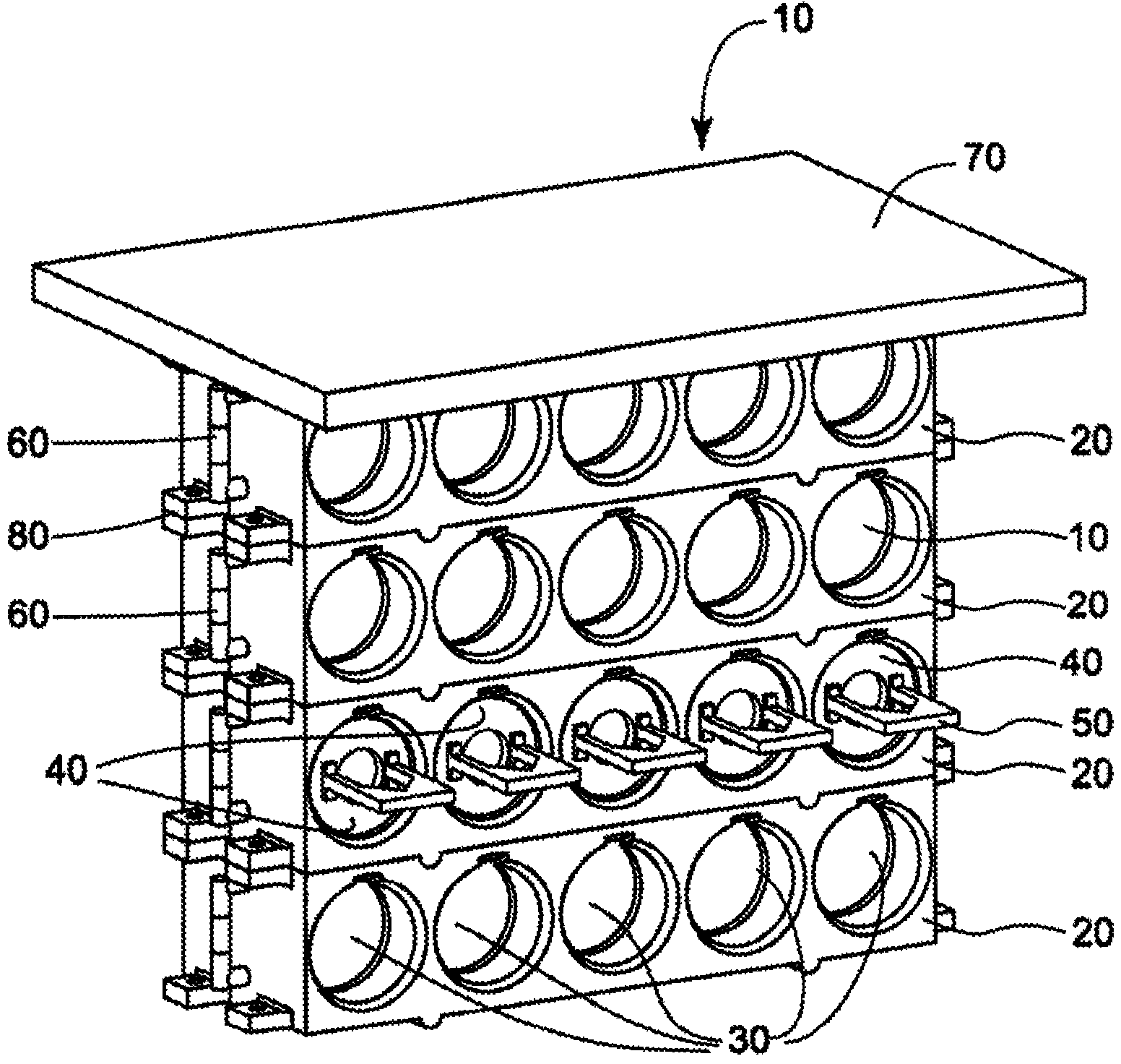
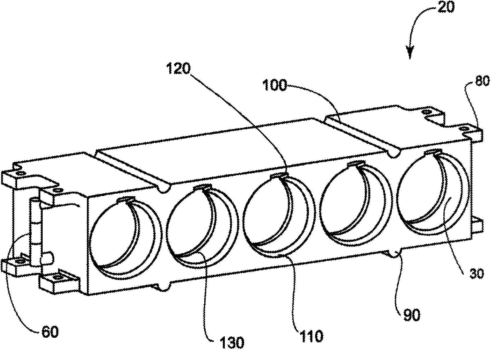
[0045] figure 1 is a perspective view of a submersible power supply 10 according to one embodiment. Such as figure 1 As seen in , the submersible power supply apparatus 10 includes a plurality of reserve battery modules 40 within reserve battery racks 20 that are stacked o...


PUM


Abstract

A submersible power supply apparatus provides the ability to provide power for recharging batteries used to operate underwater vehicles, manned and unmanned. A battery charging station apparatus containing at least one modular reserve battery magazine with a plurality of compartments is provided. A plurality of reserve battery modules may be respectively provided in the plurality of compartments, each of the plurality of reserve battery modules being configured to provide power when a reserve battery provided therein is activated.

Description

technical field [0001] This non-provisional application claims the benefit of U.S. Provisional Application No. 61 / 680,518, filed August 7, 2012. [0002] The present invention relates to subsea charging of batteries for underwater vehicles and applications using battery energy provided by charging stations. Background technique [0003] The present disclosure relates to underwater charging devices having multiple reserve battery modules to provide power in remote access applications and their use. An example of such an application is powering subsea electrical functions (e.g. backup power) such as in remote littoral zones where power is required for many purposes, such as powering submarines (manned and unmanned, including military applications). [0004] Battery selection becomes a major factor due to the energy requirements required to charge underwater vehicles in subsea conditions. Over time, primary cell degradation results in a reduction in the battery's ability to ...

Claims


Application Information

Patent Timeline
Patent Type & Authority Applications(China)
IPC IPC(8): H01M2/10H01M10/46H01M6/30H01M6/34H01M6/50H01M10/42H01M16/00H01M50/204H01M50/251
CPCH01M10/46H02J7/00B63C11/52H01M6/5033B63J99/00H01M16/00H01M2010/4278B63G8/001H01M10/4207H01M2/1077H01M10/465H01M6/34H01M6/5011H01M6/30H01M50/251H01M50/204H02J2310/42Y02E60/10H02J7/00036
Inventor 格雷戈里·L·米勒迈克尔·A·帕罗特杰弗里·C·德莫特达美施·H·巴克塔丹尼斯·迪万
Owner 艺格比奇技术公司
Learn More