
Stacking system electing method and main device

A technology of stacking system and main equipment, applied in the field of communication, can solve problems such as interruption of network communication of stacking system

Active Publication Date: 2015-03-04
MAIPU COMM TECH CO LTD
View PDF4 Cites 9 Cited by
  • Summary
  • Abstract
  • Description
  • Claims
  • Application Information

AI Technical Summary

Problems solved by technology

[0010] It can be seen from these election rules that if a member device without an uplink port in the stack system is elected as the master device, after the stack splits, the device will win the multi-activation detection according to rule c, which will inevitably lead to The network communication of the entire stack system is interrupted

Method used


Image

  • Stacking system electing method and main device
  • Stacking system electing method and main device
  • Stacking system electing method and main device

Examples


Embodiment 1

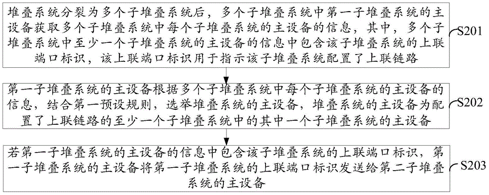
[0041] An embodiment of the present invention provides a stacking system election method, specifically as figure 2 shown, including:

[0042] S201. After the stacking system is split into multiple sub-stacking systems, the main device of the first sub-stacking system in the multiple sub-stacking systems obtains the information of the main device of each sub-stacking system in the multiple sub-stacking systems, wherein at least one of the multiple sub-stacking systems The information of the master device of the sub-stack system includes an uplink port identifier of the sub-stack system, and the uplink port identifier is used to indicate that the sub-stack system is configured with an uplink.

[0043] S202. The master device of the first sub-stacking system elects the master device of the stacking system according to the information of the master device of each sub-stacking system among the multiple sub-stacking systems, in combination with the first preset rule, wherein the ma...

Embodiment 2

[0091] An embodiment of the present invention provides a main device 10, the main device 10 is the main device of the first sub-stacking system in the multiple sub-stacking systems after the stacking system is split into multiple sub-stacking systems, such as Figure 10 As shown, the master device includes: an acquisition unit 101 and an election unit 102 .

[0092] The acquiring unit 101 is configured to acquire the information of the main device of each sub-stacking system in the plurality of sub-stacking systems, wherein the information of the main device of at least one sub-stacking system in the plurality of sub-stacking systems includes the sub-stacking An uplink port identifier of the system, where the uplink port identifier is used to indicate that the sub-stack system is configured with an uplink link.

[0093] The electing unit 102 is configured to elect the master device of the stacking system according to the information of the master device of each sub-stacking sy...


PUM


Abstract

An embodiment of the invention provides a stacking system electing method and a main device. Reliability of a network can be improved. The method includes the steps: acquiring information of a main device of each stacking subsystem among a plurality of stacking subsystems by a main device of a first stacking subsystem among the stacking subsystems after a stacking system is split into the stacking subsystems; electing a main device of the stacking system by the main device of the first stacking subsystem according to the information of the main device of each stacking subsystem among the stacking subsystems through a first preset rule. The information of the main device of at least one stacking subsystem among the stacking subsystems comprises uplink port identifiers of the stacking subsystems, the uplink port identifiers are used for indicating that the stacking subsystems are provided with uplinks, and the main device of the stacking system is a main device of one stacking subsystem among at least one stacking subsystem provided with the uplinks. The electing method is applicable to the field of communication.

Description

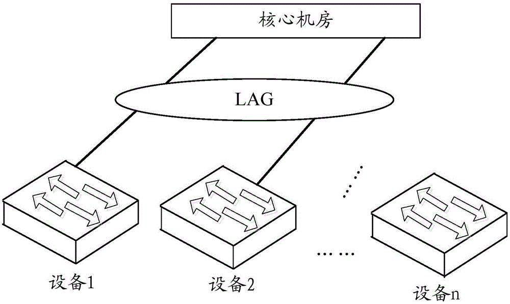
technical field [0001] The invention relates to the communication field, in particular to an election method and a master device of a stacking system. Background technique [0002] With the development of virtualization technology, the virtual switch technology represented by stacking is more and more widely used. Among them, stacking refers to a network technology that virtualizes multiple network devices into one device. Multiple network devices are stacked to form a stack system. [0003] In the actual deployment of the building LAN where the stacking system is most widely used, usually only one stacking system needs to be deployed on one floor. The architecture diagram of the stacking system is as follows: figure 1 shown. The number of stack member devices depends on the number of access users. The stacking system on each floor aggregates the uplink core equipment room through the link across devices. However, since the data links between floors are usually few and h...

Claims


Application Information

Patent Timeline
IPC IPC(8): H04L12/24
Inventor 熊德江
Owner MAIPU COMM TECH CO LTD
Learn More