
Control circuit, control method and switching mode convertor

A control circuit and control switch technology, which are applied in the direction of adjusting electrical variables, control/regulating systems, converting DC power input to DC power output, etc. , switching converter control failure, etc.

Active Publication Date: 2015-03-04
SILERGY SEMICON TECH (HANGZHOU) CO LTD
View PDF2 Cites 6 Cited by
  • Summary
  • Abstract
  • Description
  • Claims
  • Application Information

AI Technical Summary

Problems solved by technology

Due to the need to set the current detection blanking time when detecting, the minimum on-time of the second switch will be limited
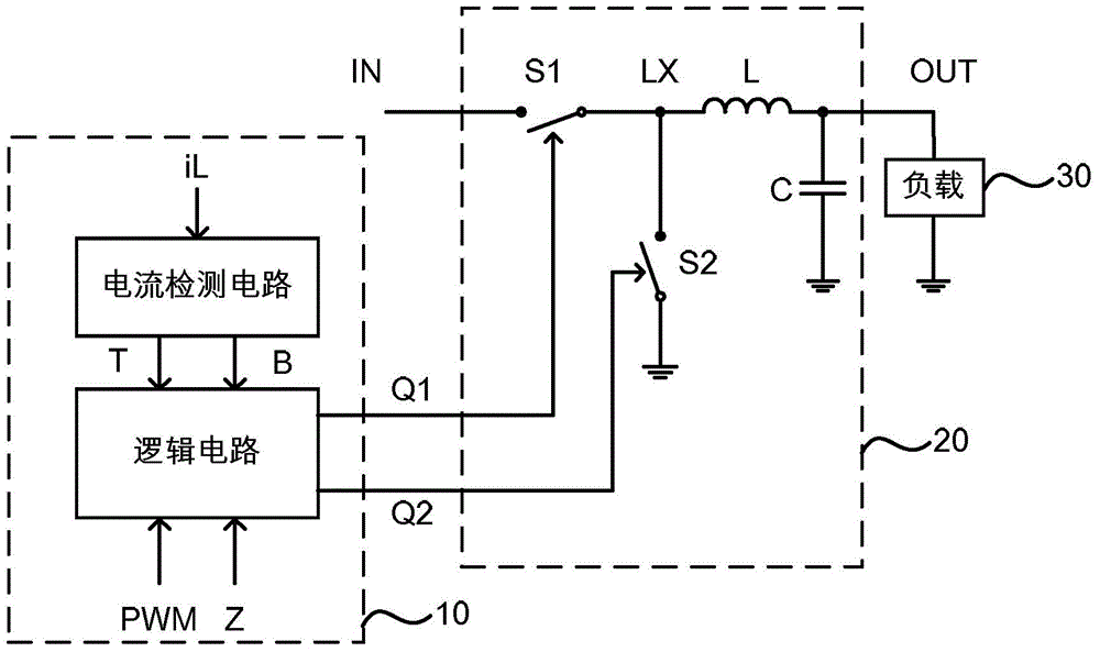
[0003] If the above control method is sampled, when the switching frequency of the first switch is high, if the duty ratio of the pulse width modulation signal PWM controlling the main switch is large, the conduction time of the second switch may be very small, even less than the current Detection of the blanking time, so that the detection of the inductor current cannot be realized (because the detection of the valley value is during the conduction period of the second switch), so that the control of the switching converter is invalid

Method used


Image

  • Control circuit, control method and switching mode convertor
  • Control circuit, control method and switching mode convertor
  • Control circuit, control method and switching mode convertor

Examples


Embodiment Construction

[0041] The present invention is described below based on examples, but the present invention is not limited to these examples. In the following detailed description of the invention, some specific details are set forth in detail. The present invention can be fully understood by those skilled in the art without the description of these detailed parts. In order not to obscure the essence of the present invention, well-known methods, procedures, procedures, components and circuits have not been described in detail.

[0042] Additionally, those of ordinary skill in the art will appreciate that the drawings provided herein are for illustrative purposes and are not necessarily drawn to scale.

[0043] Meanwhile, it should be understood that in the following description, "circuit" refers to a conductive loop formed by at least one element or sub-circuit through electrical connection or electromagnetic connection. When an element or circuit is said to be "connected to" another eleme...


PUM


Abstract

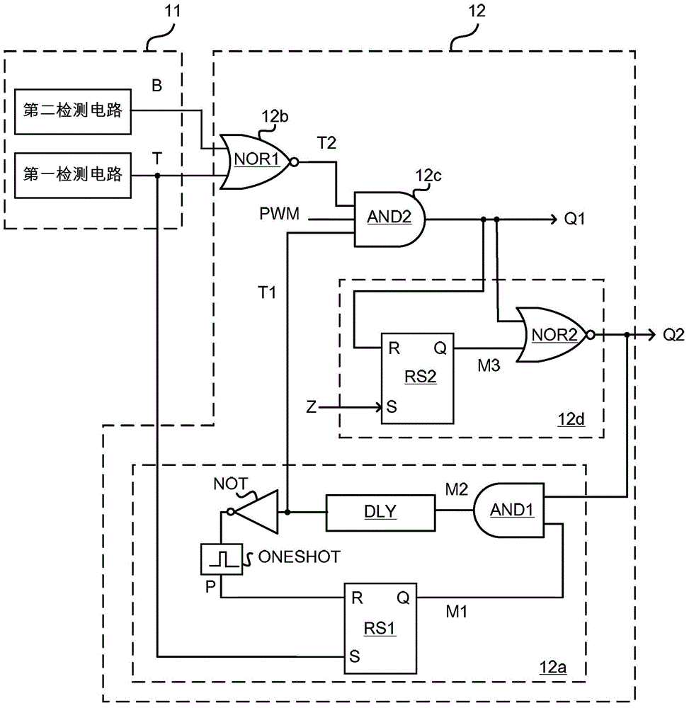
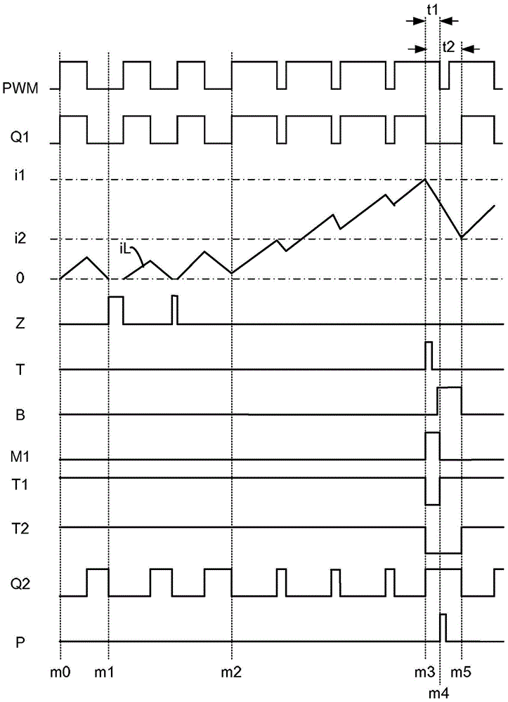
The invention discloses a control circuit, a control method and a switching mode convertor; when an inductive current is detected to rise to a first threshold value, the control enables a first switch of a power level circuit to maintain in turn-off, and a second switch to maintain in breakover for at least a first period until the inductive current is less than a second threshold value; therefore the inductive current can continuously drop at certain intervals when the switching frequency is higher and the duty cycle is larger, thereby enabling a controller to effectively detect valley values of the inductive current and maintaining the circuit control as well as ensuring the inductive current controllable.

Description

technical field [0001] The invention relates to power electronics technology, in particular to a control circuit, a control method and a switching converter. Background technique [0002] Synchronous switching converters generally use pulse width modulation (PWM, Pulse Width Modulation) signals to control the on and off of the main switch tube. When the pulse width modulation signal is active, the first switch (main power switch) is turned on , when the pulse width modulation signal is in an invalid state, the first switch is turned off, and the second switch (synchronous rectification switch) is controlled to be turned on at the same time, and the second switch is controlled to be turned off until it is detected that the inductor current drops to a predetermined valley value . When using this control method, during the inductor current detection process, the parasitic effect on the switch node will cause the excitation phenomenon, so it is necessary to wait for a period of...

Claims


Application Information

Patent Timeline
IPC IPC(8): H02M1/088H02M3/156
CPCH02M1/088H02M3/157H02M3/158H02M3/1588H02M1/0009
Inventor 安鸿峰
Owner SILERGY SEMICON TECH (HANGZHOU) CO LTD
Learn More