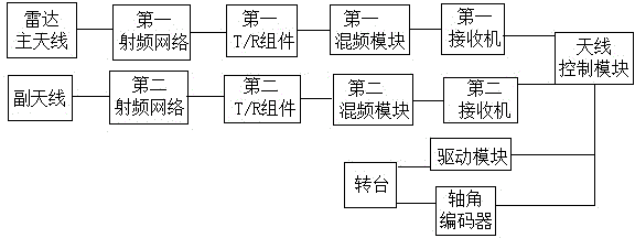
Radar system using main antenna as helical antenna
What is Al technical title?
Al technical title is built by PatSnap Al team. It summarizes the technical point description of the patent document.
A helical antenna and radar system technology, applied in the field of signal processing, can solve the problems of not fully reflecting the functions of the radar system, not being very comprehensive in the functions of the radar system, and not providing technical means for implementation, and achieving novel design, enhanced gain, accurate Effects of the signal reception function
Inactive Publication Date: 2015-03-04
WUXI WISEN INNOVATION TECH
View PDF7 Cites 1 Cited by
Summary
Abstract
Description
Claims
Application Information
AI Technical Summary
This helps you quickly interpret patents by identifying the three key elements:
Problems solved by technology
Method used
Benefits of technology
Problems solved by technology
[0003] The patent number is 201210517630.7, and the patent name is a radar system. This patent proposes solutions to the problems in the prior art, but the functions of the radar system in this patent are not very comprehensive and do not fully reflect the functions of the radar system.
[0004] The patent number is 201180012113.8, and the patent name is a radar system. This patent points out the problems of radar system size and cost in the prior art, and also provides a certain solution, but the solution is too idealized and does not give Specific implementation technical means
[0005] At the same time, the commonly used radar systems in the prior art generally have the problems of complex structure and high power consumption, which need further improvement
Method used
Image
Click on the blue label to locate the original text in one second.
Reading with bidirectional positioning of images and text.
Examples
Embodiment Construction
[0025] The embodiments of the present invention are described in detail below. Examples of the embodiments are shown in the accompanying drawings, wherein the same or similar reference numerals indicate the same or similar elements or elements with the same or similar functions. The following embodiments described with reference to the accompanying drawings are exemplary, and are only used to explain the present invention, and cannot be construed as limiting the present invention.
[0026] Those skilled in the art can understand that the related modules involved in the present invention and the functions implemented are to carry conventional computer software programs or programs in the prior art on the improved hardware and the devices, devices or systems that it constitutes. Relevant agreements can be realized, and it is not an improvement of computer software programs or relevant agreements in the prior art. For example, an improved computer hardware system can still implement...
PUM
Abstract
The invention discloses a radar system using a main antenna as a helical antenna. The radar system comprises a radar main antenna, a first RF network, a first T / R assembly, a first mixing module, a first receiving machine, an antenna control module, a secondary antenna, a second RF network, a second T / R assembly, a second mixing module, a second receiving machine, a driving module, a rotary table and a shaft angle encoder; the radar main antenna and the secondary antenna are both positioned on the rotary table; the radar main antenna, the first RF network, the first T / R assembly, the first mixing module, the first receiving machine and the antenna control module are connected in a sequence; the secondary antenna, the second RF network, the second T / R assembly, the second mixing module, the second receiving machine and the antenna control module are sequentially connected in a sequence. According to the radar system, the design of the main antenna and the secondary antenna enables accurate signal receiving of the radar system, and therefore, the problems like inaccurate receiving caused by error can be reduced; meanwhile, the rotary table is controlled through a code, so that the rotating angle of the rotary table is accurate, and as a result, the accurate signal receiving function can be realized.
Description
Technical field [0001] The invention discloses a radar system whose main antenna is a helical antenna, which belongs to the technical field of signal processing. Background technique [0002] In recent decades, there have been amazing developments in antennas and radars, but there have been no major breakthroughs in the basic courtyard. At present, the types and shapes of antennas are emerging in endlessly, performance requirements are getting higher and higher, and the application fields continue to expand. The urgent needs of military equipment and national economy promote and lead the rapid development of antenna theory and technology. In many fields of modern science and technology, Automatic control technology plays an increasingly important role. The so-called automatic control refers to the use of additional equipment and devices to make the equipment, equipment or production process automatically follow a predetermined law without direct participation of people. In recen...
Claims
Application Information
Patent Timeline
Application Date:The date an application was filed.
Publication Date:The date a patent or application was officially published.
First Publication Date:The earliest publication date of a patent with the same application number.
Issue Date:Publication date of the patent grant document.
PCT Entry Date:The Entry date of PCT National Phase.
Estimated Expiry Date:The statutory expiry date of a patent right according to the Patent Law, and it is the longest term of protection that the patent right can achieve without the termination of the patent right due to other reasons(Term extension factor has been taken into account ).
Invalid Date:Actual expiry date is based on effective date or publication date of legal transaction data of invalid patent.