
Device with pulverized coal separator between coal mill and burner

A separator and coal mill technology, which is applied in the fields of devices, boilers, and utility boilers with pulverized coal separators, can solve the problems of low safety factor, insufficient combustion, unstable ignition and combustion, etc., and achieve excellent installation and use environment. , Conducive to installation and use, maintenance and repair effect

Inactive Publication Date: 2015-03-04
中节环(北京)环境科技股份有限公司
View PDF8 Cites 0 Cited by
  • Summary
  • Abstract
  • Description
  • Claims
  • Application Information

AI Technical Summary

Problems solved by technology

②. The present invention changes the situation that the thick-thin separation device is always installed at the position of the burner body, and overcomes the excessive deviation of the wind speed of the nozzles on both sides of the burner caused by the installation of the thick-thin separation device in the burner with limited volume and too short length. Large, unstable ignition and combustion, insufficient combustion, low safety factor and many other defects and disadvantages

Method used


Image

  • Device with pulverized coal separator between coal mill and burner
  • Device with pulverized coal separator between coal mill and burner
  • Device with pulverized coal separator between coal mill and burner

Examples


specific Embodiment approach 1

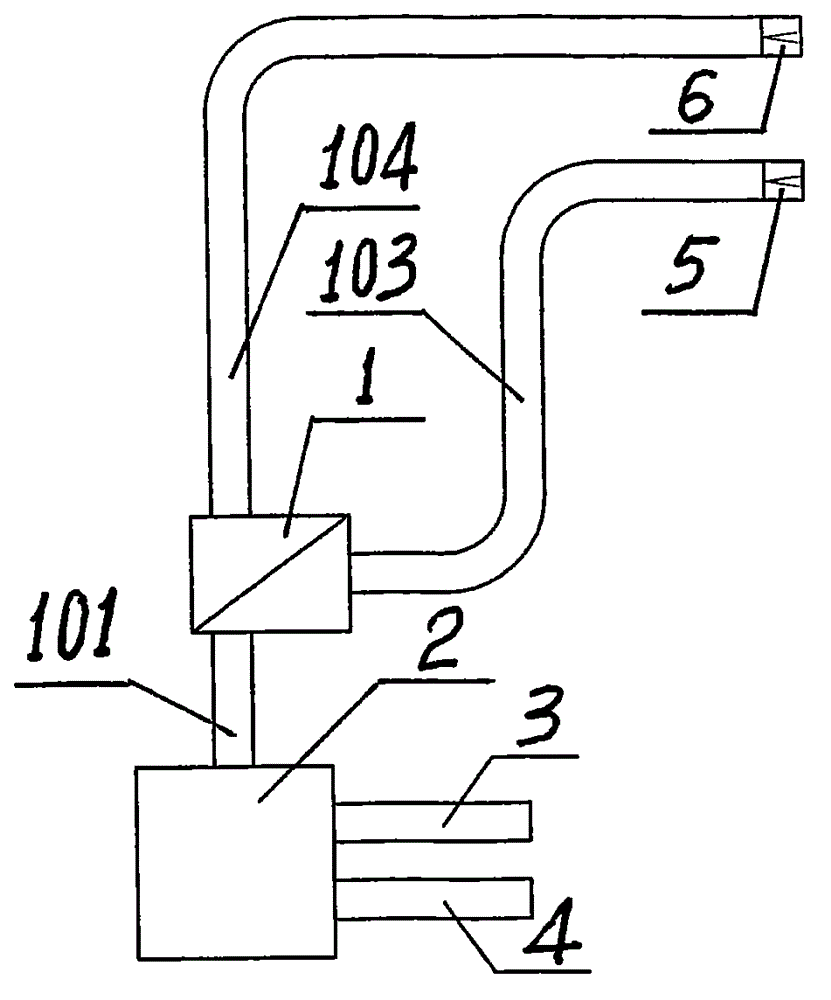
[0036] The "device for setting a pulverized coal separator between the coal mill and the burner" of the present invention will be described in detail below in conjunction with the accompanying drawings. As attached to the manual figure 1 , 2 , 4, 5, and 6 show:

[0037] A device for setting a pulverized coal separator between a coal mill and a burner, the separator consisting of a mixing tube 101, a separating tube 102, a concentrated pulverized coal tube 103, a thin pulverized coal tube 104, an adjusting shaft 105, and a separating plate 106 1 and coal mill 2, air pipe 3, coal pipe 4, thick burner nozzle 5, and light burner nozzle 6;

[0038] A pulverized coal separator device is arranged between the coal mill and the burner, and its mixing pipe 101 and separation pipe 102, separation pipe 102, thick pulverized coal pipe 103 and light pulverized coal pipe 104 are all fixedly connected, and its separation pipe 102 It is connected with the adjustment shaft 105 in a rotating ...

specific Embodiment approach 2

[0044] Carry out by specific embodiment one, just: just as specification attached figure 2 , 6 As shown, the thick pulverized coal pipe 103 and the light pulverized coal pipe 104 are implemented in parallel with each other at a position between the two; the expected good effect is also obtained.


PUM


Abstract

The invention provides a device with a pulverized coal separator between a coal mill and a burner and relates to the boiler technical field. The key technology of the pulverized coal separator is adopted, a mixing pipe and a separation pipe and the separation pipe and a dense pulverized coal pipe and a dilute pulverized coal pipe of the device are fixedly connected with each other; the separation pipe is flexibly connected with an adjustment shaft in a rotating mode; the adjustment shaft is fixedly connected with a separation plate; an air pipe and a coal pipe of the device is fixedly connected with the coal mill; an outlet end of the coal middle is fixedly connected with an inlet end of the mixing pipe which is arranged on the separator; an outlet end of the dense pulverized coal pipe which is arranged on the separator is fixedly connected with an inlet end of a dense burner nozzle; an outlet end of the dilute pulverized coal pipe which is arranged on the separator is fixedly connected with an inlet end of a dilute burner nozzle. The device with the pulverized coal separator between the coal mill and the burner is applied to the boiler burning and has the advantages of being unique and novel in design, scientific and reasonable in design, simple and skillful in structure, stable and reliable in effect, convenient to produce, low in cost, convenient to use and good in benefit.

Description

technical field [0001] The invention relates to a device for installing a pulverized coal separator between a coal mill and a burner, and relates to the technical field of boilers; in particular, it relates to the technical field of power plant boilers; in particular, it relates to the technical field of a device for installing a pulverized coal separator between a coal mill and a burner. Background technique [0002] In the ignition and combustion process of power plant boilers, in order to improve the stability of coal ignition and combustion, the pulverized coal burner is usually equipped with a thick-thin separation device on the burner body, that is, a vertical vertical thick-thin separation device is used at the position of the burner nozzle. Or a horizontal thick-lean separation device, such as the WR burner designed by the American Combustion Engineering Company, the flame-stabilized ship-type DC burner developed by Tsinghua University, and the horizontal thick-lean p...

Claims


Application Information

Patent Timeline
IPC IPC(8): F23K1/00F23K3/02
Inventor 韩剑锋杨秋东陈安合
Owner 中节环(北京)环境科技股份有限公司
Learn More