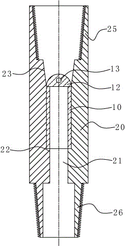
Drill pipe drift assembly
A technology of drift gauges and drill pipes, which is applied in the direction of earthwork drilling, wellbore/well components, etc., and can solve the problems of failing to meet the diameter requirements and damaging tools, etc.
- Summary
- Abstract
- Description
- Claims
- Application Information
AI Technical Summary
Problems solved by technology
Method used
Image
Examples
Embodiment Construction
[0015] The specific implementation manner of the present invention will be further described below in conjunction with the accompanying drawings.
[0016] Such as figure 1 As shown, a drill pipe gauge assembly of the present invention includes a circular tubular gauge body 10, a lifting lug 12 fixedly connected to the top end of the gauge body, and a bearing with an axial through hole. Bracket 20, the middle section of the through hole 21 that is located in the support seat 20 and can support the supporting step 22 of the diameter gauge body, the inner cavity of the part above the supporting step 22 is larger than the diameter gauge body 20, and the bearing The top of the bracket 20 is provided with a top joint 25 that can be connected with the bottom end of the drilling rod that needs to pass through. When the diameter of the circular tube type diameter gauge is passed, the existing fluid in the drill pipe passes through the middle of the diameter gauge so that the diameter ...
PUM
 Abstract
Description
Claims
Application Information
 - R&D Engineer
- R&D Manager
- IP Professional
- Industry Leading Data Capabilities
- Powerful AI technology
- Patent DNA Extraction
Browse by: Latest US Patents, China's latest patents, Technical Efficacy Thesaurus, Application Domain, Technology Topic, Popular Technical Reports.
© 2024 PatSnap. All rights reserved.Legal|Privacy policy|Modern Slavery Act Transparency Statement|Sitemap|About US| Contact US: help@patsnap.com


