
Steel wire retainer ring shaping mechanism

A steel wire retaining ring and steel wire technology, which is applied in the field of steel wire retaining ring shaping mechanism, can solve the problems of steel wire retaining ring deformation, product damage, and difficulty in precision control, and achieve the effect of neat and high precision

Active Publication Date: 2015-03-04
ANHUI NINGGUO DONGBO FASTENER
View PDF7 Cites 2 Cited by
  • Summary
  • Abstract
  • Description
  • Claims
  • Application Information

AI Technical Summary

Problems solved by technology

[0002] In the retaining ring processing, in order to facilitate processing, the steel retaining ring needs to be wound into a spring shape on the forming machine, however, the steel wire retaining ring after winding is seriously deformed, and the retaining ring needs to be shaped after heat treatment
[0003] In the prior art, due to the high hardness of the steel wire retaining ring, the staff carry out manual shaping one by one, which has the disadvantages of high labor intensity, unsatisfactory product effect after shaping, difficult precision control, and easy damage to the product

Method used


Image

  • Steel wire retainer ring shaping mechanism

Examples


Embodiment Construction

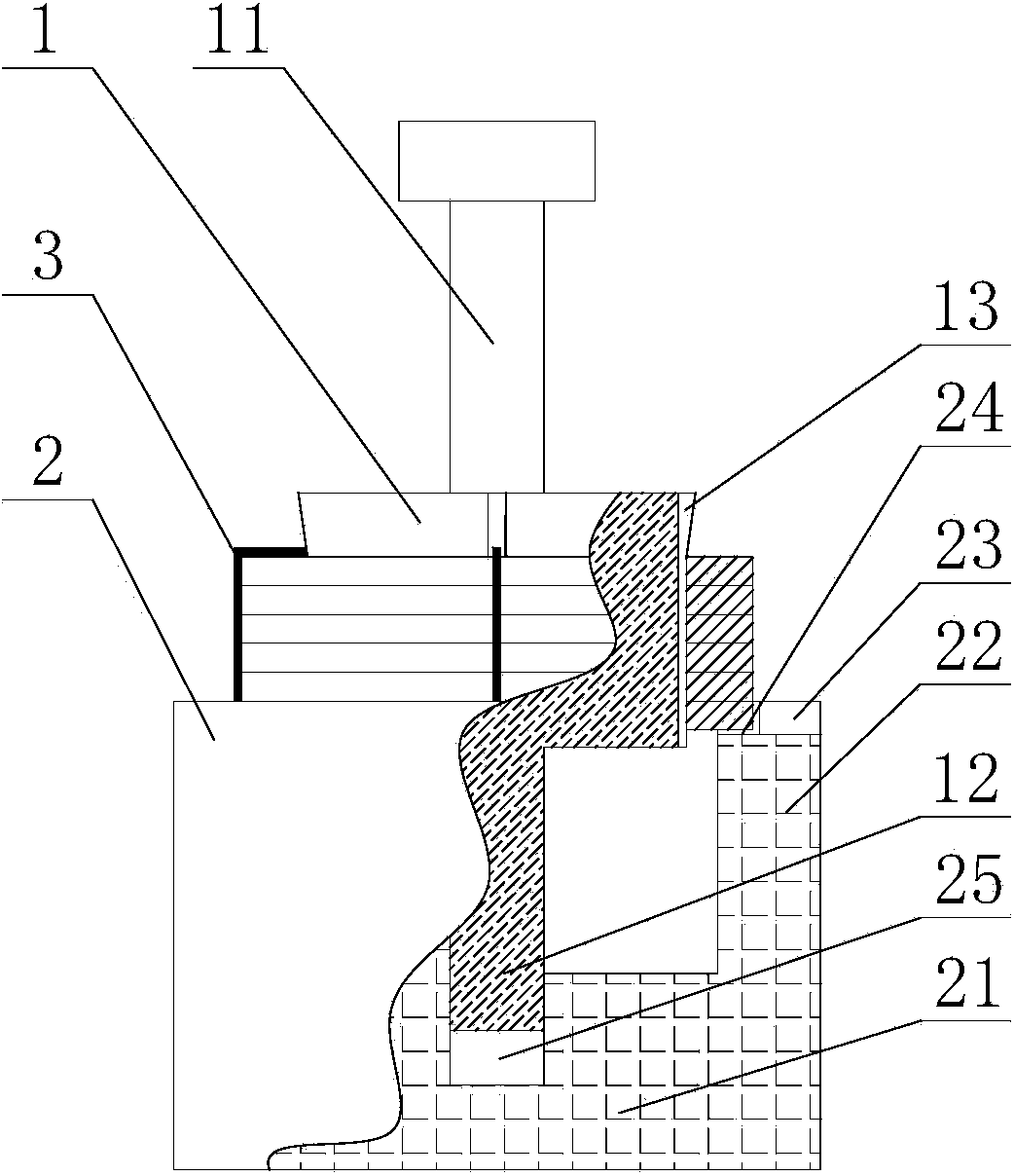
[0015] Such as figure 1 as shown, figure 1 It is a structural schematic diagram of a wire retaining ring shaping mechanism proposed by the present invention.

[0016] refer to figure 1 , a steel wire retaining ring shaping mechanism proposed by the present invention, comprising: a cylindrical core 1, a sleeve 2 and a fastening steel wire 3;

[0017] The middle part of the upper surface of the cylindrical core body 1 is provided with an upwardly protruding force bearing block 11, and its lower surface is provided with a downwardly protruding guide pillar 12. The outer diameter of the cylindrical core body 1 is A1, and the outer diameter of its upper part is A2. The inner diameter of the shaping retaining ring is D1, the outer diameter of the retaining ring is D2, A1<D1<A2, specifically, A2 is 1.05-1.1 times of A1, and the side wall of the cylindrical core 1 is provided with a shaft from the upper surface to the downward direction. A plurality of grooves 13 extending to the d...


PUM


Abstract

The invention discloses a steel wire retainer ring shaping mechanism. The mechanism comprises a cylinder core body, a sleeve and a fastening steel wire, wherein a stress block upwards projected is arranged in the middle of the upper surface of the cylinder core body, and a guide support column downwards extending is arranged on the lower surface of the cylinder core body; a groove downwards axially extending from the upper surface is formed in the side wall of the cylinder core body; the outer wall of the cylinder core body and the inner wall of a steel wire retainer ring to be shaped fit in shape; the sleeve comprises a baseplate and a cylindrical side wall, and coats the external of the cylinder core body; an annular limiting piece upwards extending from the top surface is arranged at the top of the cylindrical side wall, and is coaxial with the cylindrical side wall; a notch is formed in the inner wall of the annular limiting piece, and is opposite to the groove of the cylinder core body; a guide through hole axially downwards extending from the upper surface is formed in the baseplate, and fits the guide support column for use; and the fastening steel wire fastens the steel wire retainer ring to be shaped on the outer wall of the cylinder core body, and is positioned in the groove and the notch. The mechanism is simple in structure and easy in operation, and realizes the batch shaping of the steel wire retainer ring.

Description

technical field [0001] The invention relates to the technical field of retaining ring processing, in particular to a steel wire retaining ring shaping mechanism. Background technique [0002] In the retaining ring processing, in order to facilitate processing, the steel wire retaining ring needs to be wound into a spring shape on the forming machine. However, the steel wire retaining ring after winding is seriously deformed, and the retaining ring needs to be shaped after heat treatment. [0003] In the prior art, due to the high hardness of the steel wire retaining rings, the workers manually shape them one by one, which is labor-intensive, the product effect after shaping is not ideal, the precision control is difficult, and it is easy to cause damage to the product. Therefore, how to carry out batch reshaping of the wound steel wire retaining rings, so that the products are neat, with high precision, and no secondary deformation occurs during the reshaping process, has be...

Claims


Application Information

Patent Timeline
Patent Type & Authority Applications(China)
IPC IPC(8): B23P6/00
CPCB23P6/00
Inventor 张吴斌王尔凤戴婧
Owner ANHUI NINGGUO DONGBO FASTENER
Learn More