
Backlight module and display with the same

A technology for backlight modules and displays, applied in the directions of light guides, optics, instruments, etc., can solve the problems of low assembly efficiency, many components, and increase the thickness of backlight modules, so as to achieve narrow frame design, reduce manufacturing costs, and facilitate the assembly process. Effect

Inactive Publication Date: 2015-02-25
TCL CHINA STAR OPTOELECTRONICS TECH CO LTD
View PDF13 Cites 18 Cited by
  • Summary
  • Abstract
  • Description
  • Claims
  • Application Information

AI Technical Summary

Problems solved by technology

[0004] However, during the assembly process, due to errors in the assembly process of the light guide plate and the plastic frame, it is inevitable that there will be an assembly gap between the light guide plate and the plastic frame, and because the plastic frame itself has a certain thickness, this is inevitable. It will increase the thickness of the backlight module, thereby increasing the overall thickness of the liquid crystal display device, which cannot meet the mainstream needs of the market.
In addition, the existing backlight module requires more components and complex structure, which increases the manufacturing cost; moreover, the assembly process of the plastic frame and the light guide plate is relatively cumbersome, and the assembly efficiency is low

Method used


Image

  • Backlight module and display with the same
  • Backlight module and display with the same
  • Backlight module and display with the same

Examples


Embodiment Construction

[0031] The technical solutions in the embodiments of the present invention will be clearly and completely described below with reference to the accompanying drawings in the embodiments of the present invention. Obviously, the described embodiments are only a part of the embodiments of the present invention, but not all of the embodiments. Based on the embodiments of the present invention, all other embodiments obtained by those of ordinary skill in the art without creative efforts shall fall within the protection scope of the present invention.

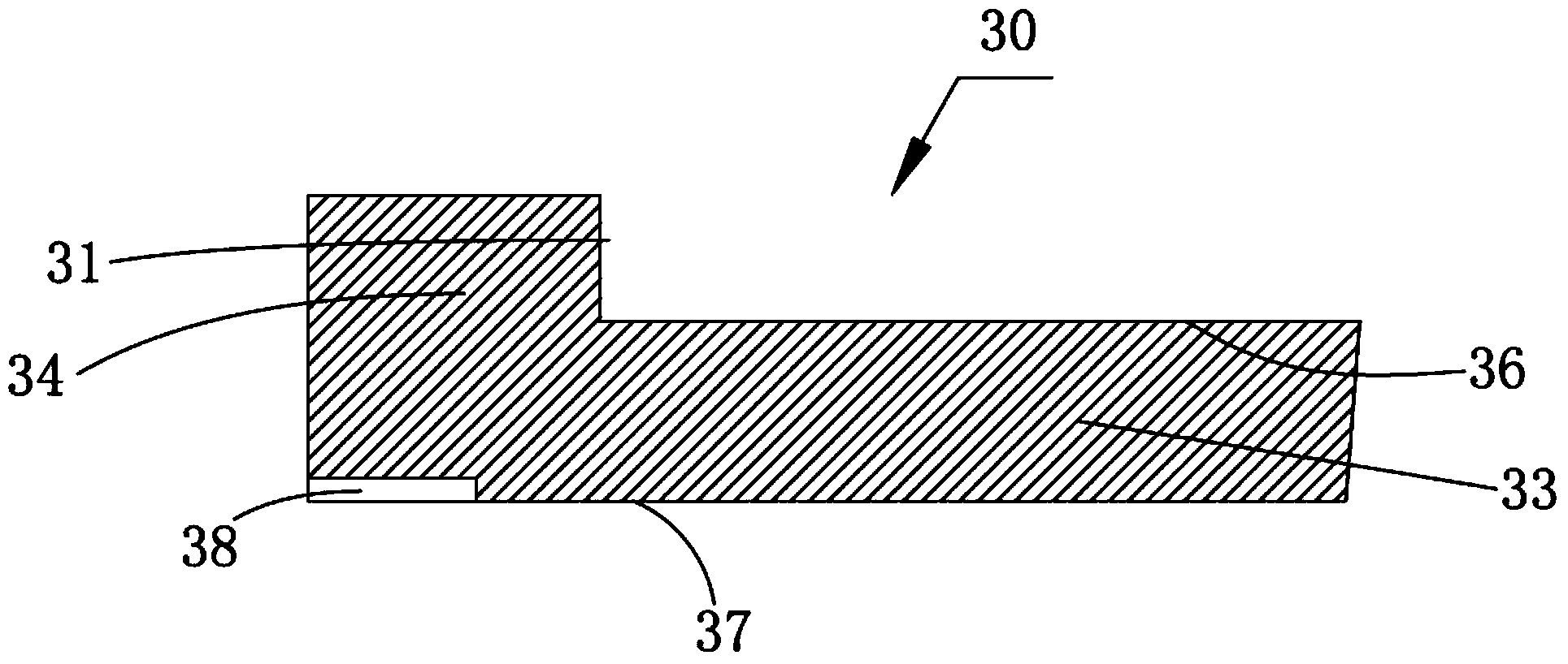
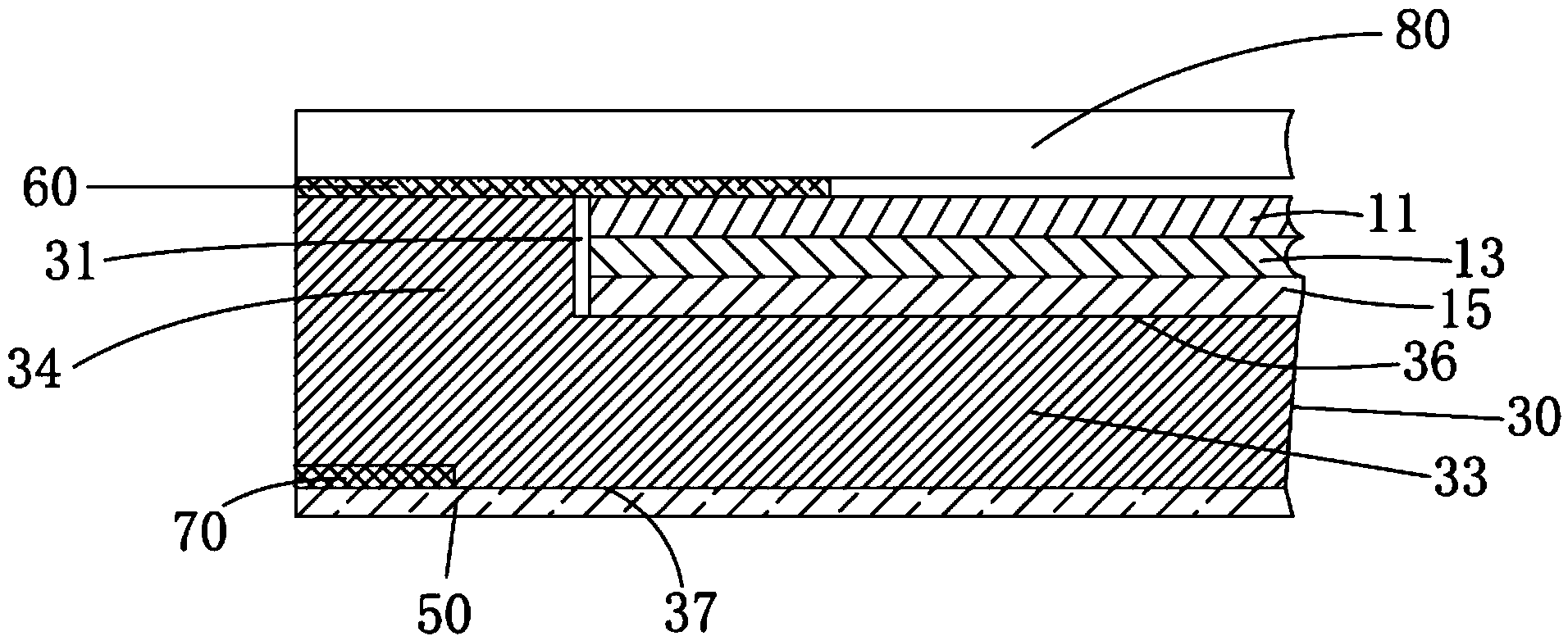
[0032] see figure 1 , figure 1 It is a partial cross-sectional schematic diagram of a backlight module according to an embodiment of the present invention. like figure 1 As shown, the backlight module 100 according to an embodiment of the present invention may be a liquid crystal backlight module, which includes an optical film 10 , a light guide plate 30 and a reflection sheet 50 . The optical film 10 is disposed on the light guid...


PUM

PropertyMeasurementUnit
reflectanceaaaaaaaaaa

Abstract

The invention provides a backlight module. The backlight module comprises an optical membrane, a light guide plate, a reflection piece and first adhesive tape. The optical membrane is arranged in the light guide plate. An open groove is formed in the edge of the lower surface of the light guide plate. The open groove is used for containing the first adhesive tape. The peripheral edge of the reflection piece adheres to the side, opposite to the optical membrane, of the light guide plate through the first adhesive tape. The reflection piece is fixed to the light guide plate through the first adhesive tape. The invention further provides a display. By means of the backlight module, the optical membrane and the reflection piece are fixed under the condition that no rubber frame exists, and therefore back plates, rubber frames and other parts in existing backlight modules are omitted, the overall thickness of the backlight module can be reduced, and the narrow-edge frame design is achieved. In addition, the backlight module is simple in structure, and therefore the manufacturing cost is reduced, and the assembly process of the whole backlight module is made more convenient and rapid.

Description

technical field [0001] The invention relates to the field of light-emitting display, in particular to a backlight module and a display having the backlight module. Background technique [0002] With the continuous development of backlight display technology, liquid crystal display devices such as liquid crystal displays (LCDs) have been widely used in electronic products such as mobile phones, digital cameras, and personal digital assistants (PDAs) as display components. With the narrowing of the frame of electronic products and the continuous advancement of technology in the liquid crystal industry, the large size of LCD screen display and the thinning of the frame have become more and more mainstream demands in the market. [0003] As an important component of a liquid crystal display device, the backlight module has become a trend of framed design. A narrow frame means that the screen area that can be seen under the same size screen is larger and the visual effect is bett...

Claims


Application Information

Patent Timeline
Patent Type & Authority Applications(China)
IPC IPC(8): G02F1/13357G02B6/00
CPCG02B6/0035G02F1/133615G02F1/133607G02F1/13
Inventor 周革革
Owner TCL CHINA STAR OPTOELECTRONICS TECH CO LTD
Learn More