
Lifting high-speed roller bed conveying mechanism

A technology of conveying mechanism and lifting drive motor, which is applied in the direction of conveyors, conveyor objects, mechanical conveyors, etc.

Active Publication Date: 2015-02-25
ANHUI RUIXIANG IND
View PDF4 Cites 9 Cited by
  • Summary
  • Abstract
  • Description
  • Claims
  • Application Information

AI Technical Summary

Problems solved by technology

[0002]In the current automobile welding production line, the lifting roller bed conveyor is the most common form of transportation on the welding line. Currently, the common lifting roller bed conveyor mechanism exists The slow speed cannot meet the requirements of high-tac production, the lifting height of the trolley fixture is not synchronized, the repeat positioning accuracy is poor, and the stability of the trolley fixture is poor during transportation, etc.

Method used


Image

  • Lifting high-speed roller bed conveying mechanism
  • Lifting high-speed roller bed conveying mechanism
  • Lifting high-speed roller bed conveying mechanism

Examples


Embodiment Construction

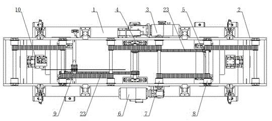
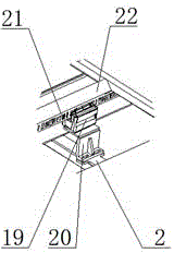
[0019] like figure 1 , figure 2 As shown, a lifting high-speed roller bed conveying mechanism includes a base 1, a lifting drive unit on the base 1, a lifting platform 2, a roller conveying device on the lifting platform 2, a guiding positioning device, and a trolley full-range identification and positioning device; figure 2 As shown, a lifting drive unit is installed on the base 1, and the lifting drive unit includes a lifting drive motor 3, a transmission main shaft 4, two synchronous belts 23 and two lifting crankshafts 5, and the lifting drive motor 3 Linked to the transmission main shaft 4, the transmission main shaft 4 constitutes a synchronous transmission device through two synchronous belts 23 and two lifting crankshafts 5, the torque of the lifting driving motor 3 can be evenly and synchronously transmitted to the two lifting crankshafts 5, The lifting platform 2 is lifted and lowered smoothly and synchronously.

[0020] like figure 2 As shown, a roller convey...


PUM


Abstract

The invention discloses a lifting high-speed roller bed conveying mechanism. The mechanism comprises a base, a lifting platform, a trolley whole-course recognizing and positioning device, a lifting positioning device and a trolley clamp, wherein a lifting driving unit is installed on the base and comprises a lifting driving motor, a transmission spindle, a synchronous belt and a lifting crankshaft, an idler wheel conveying device is installed on the lifting platform and comprises a conveyance driving motor, a driving idler wheel and a driven idler wheel, and the lifting positioning device is installed between the machine frame and the lifting platform and comprises a guiding bearing and a guiding pillar. The mechanism is used in a high-speed flexible welding conveyance system and has the advantages of being capable of achieving flexible and high-speed transmission, stable in transmission, accurate in positioning and the like.

Description

technical field [0001] The invention relates to a conveying mechanism, in particular to a lifting and high-speed roller bed conveying mechanism. Background technique [0002] In the current automobile welding production line, the lifting roller bed conveying is the most common conveying form on the welding assembly line. At present, the ordinary lifting roller bed conveying mechanism has a slow running speed and cannot meet the high-tact production requirements, and the lifting height of the trolley fixture is not high enough. Synchronization, poor repeatability positioning accuracy, poor stability when transporting trolley fixtures, etc. [0003] 1. Problems to be solved [0004] Aiming at the problems existing in the prior art, the object of the present invention is to provide a lifting high-speed roller bed conveying mechanism, which has the characteristics of fast transmission speed, compact structure, high precision and stable operation, so it is suitable for automobil...

Claims


Application Information

Patent Timeline
Patent Type & Authority Applications(China)
IPC IPC(8): B65G35/00B65G41/00
Inventor 戴荣杰刘会丙徐丽后世华张世飞叶朝国
Owner ANHUI RUIXIANG IND
Learn More