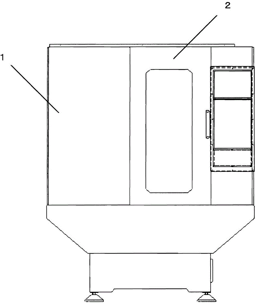
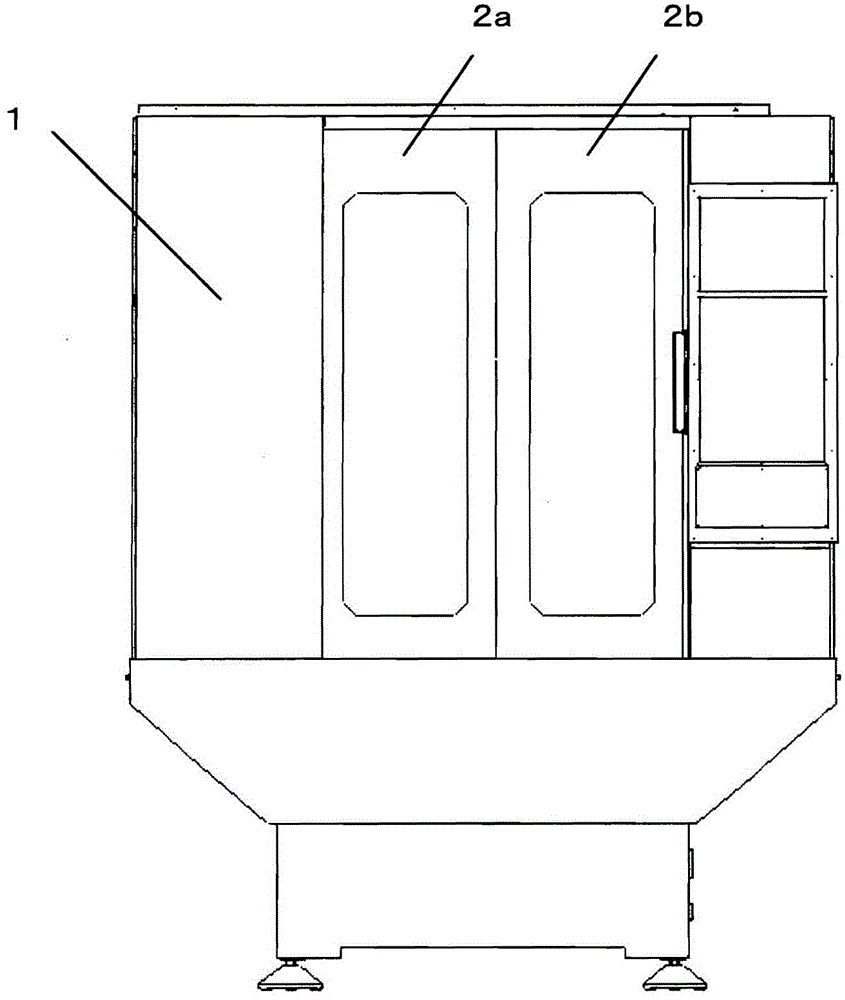
Machine tool having protective cover
A technology for protective covers, machine tools, applied in the direction of manufacturing tools, maintenance and safety accessories, metal processing machine parts, etc., can solve the method of grounding a moving door without mentioning, without describing the method of grounding a moving door, no Describe issues such as the method of electrical connection between the door and the fixed cover
- Summary
- Abstract
- Description
- Claims
- Application Information
AI Technical Summary
Problems solved by technology
Method used
Image
Examples
Embodiment approach 1
[0038] FIG. 8 is a diagram for explaining Embodiment 1. FIG.
[0039] In Embodiment 1, the leaf spring 3 is used as the conductive member. Such as Figure 8AAs shown in FIG. 1 , the leaf spring 3 as a conductive member is fixed to the splash guard main body 1 using fixing bolts 4 . Next, the leaf spring 3 comes into contact with the side surface of the door 2 when the door 2 is assembled in a predetermined position. The leaf spring 3 is a spring that expands outward. The portion of the door 2 that the leaf spring 3 contacts is made of a metal surface that is not painted. Through the above operations, the door 2 is in a state of being grounded to the splash guard main body 1 . in such as Figure 8B Even when the leaf spring 3 is fixed to the door 2 using the fixing bolts 4 as shown, the part of the splash guard main body 1 that contacts the leaf spring 3 is a metal surface that is not painted. In addition, the contact part of the leaf spring 3 may be a machined surface or...
Embodiment approach 2
[0043] FIG. 9 is a diagram for explaining Embodiment 2. FIG.
[0044] Regarding the method described above, Embodiment 2 is a mode in which the coil spring 5 is used instead of the leaf spring 3 of Embodiment 1 as the conductive member. Figure 9A An embodiment in which the coil spring 5 is fixed on the splash guard main body 1 is shown. Figure 9B An embodiment in which the coil spring 5 is fixed to the door 2 is shown.
[0045] In addition, the coil spring supporting member 7 is as Figure 9A As shown, the parts supporting the coil spring 5 in the direction of pressing the side surface of the splash guard main body 1, or as Figure 9B As shown, the member supports the coil spring 5 in the direction of pressing the side surface of the door 2 . By using the coil spring supporting member 7, it is possible to prevent the coil spring 5 from bending, and to stably contact the coil spring 5 with the facing member. In addition, the coil spring 5 is provided to be replaceable, an...
Embodiment approach 3
[0047] FIG. 10 is a diagram for explaining Embodiment 3. FIG. Embodiment 3 is an aspect in which the combination of the coil spring 5 and the slider 6 is used instead of the plate spring 3 of Embodiment 1. As shown in FIG. Figure 10A The embodiment in which the coil spring 5 and the slider 6 are fixed on the main body 1 of the splash guard is illustrated. Figure 10B An embodiment in which the coil spring 5 and the slider 6 are fixed on the door 2 is illustrated.
[0048] In addition, the coil spring support member 7 is as Figure 9A As shown, the parts supporting the coil spring 5 in the direction of pressing the side surface of the splash guard main body 1, or as Figure 9B As shown, the member supports the coil spring 5 in the direction of pressing the side surface of the door 2 . By using the coil spring supporting member 7, the coil spring 5 can be prevented from bending, and the coil spring 5 or the slider 6 can be brought into stable contact with the facing member. ...
PUM
 Abstract
Description
Claims
Application Information
 - R&D
- Intellectual Property
- Life Sciences
- Materials
- Tech Scout
- Unparalleled Data Quality
- Higher Quality Content
- 60% Fewer Hallucinations
Browse by: Latest US Patents, China's latest patents, Technical Efficacy Thesaurus, Application Domain, Technology Topic, Popular Technical Reports.
© 2025 PatSnap. All rights reserved.Legal|Privacy policy|Modern Slavery Act Transparency Statement|Sitemap|About US| Contact US: help@patsnap.com


