
Split type photovoltaic terminal box with cable protection structure

A cable protection, split-type technology, applied in the field of solar photovoltaic applications, can solve problems such as large lateral tension and bending tension, difficult cable stretching, and cracking of the cable sheath

Inactive Publication Date: 2015-02-18
安徽华成电子科技有限公司
View PDF7 Cites 9 Cited by
  • Summary
  • Abstract
  • Description
  • Claims
  • Application Information

AI Technical Summary

Problems solved by technology

However, the junction box can only transmit the current generated by the solar energy of 60 polycrystalline modules in the transmission loop, so multiple junction boxes are needed to realize the transmission of the current generated by the solar energy of the multi-chip polycrystalline modules in the transmission loop, which increases virtually. cost
Moreover, the cables of the junction box are subject to large lateral tension and bending tension at the outlet of the junction box, which not only makes it difficult to stretch the cables in all directions, but also easily cracks the outer skin of the cables here, resulting in electric leakage.

Method used


Image

  • Split type photovoltaic terminal box with cable protection structure
  • Split type photovoltaic terminal box with cable protection structure
  • Split type photovoltaic terminal box with cable protection structure

Examples


Embodiment Construction

[0017] In order to understand the present invention more clearly, the present invention will be further described below in conjunction with the accompanying drawings and specific embodiments.

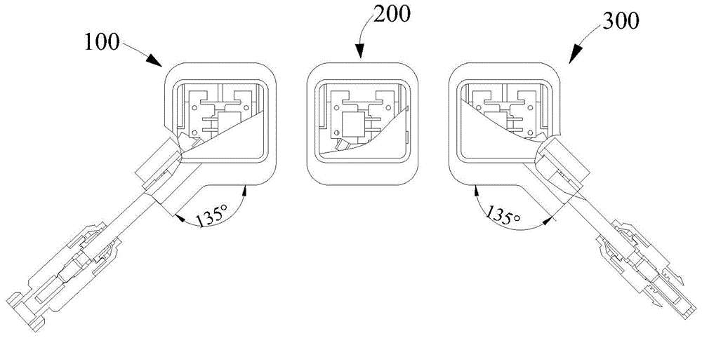
[0018] Split photovoltaic junction box with cable protection structure, such as figure 1 As shown, it is composed of a left box assembly 100, a middle box assembly 200 and a right box assembly 300. The left box assembly 100, the middle box assembly 200 and the right box assembly 300 are independent of each other and used together.

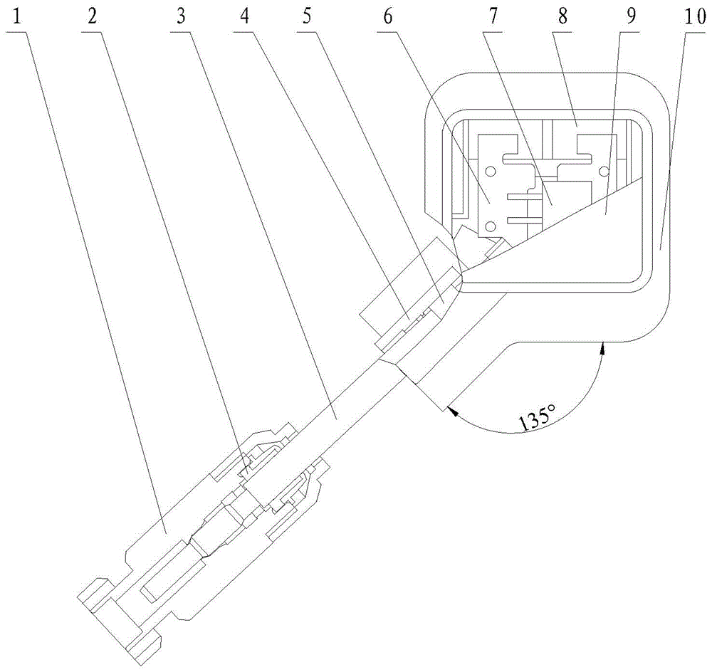
[0019] Such as figure 2 As shown, the left box body assembly 100 includes a left box body 10 and a left box cover 9, and the left box cover 9 can be snapped on the left box body 10. There are conductors and a chip diode 7 inside the left box body 10. The conductor is two metal parts 6, the chip diode 7 is located between the two metal parts 6, the chip diode 7 is welded to the two metal parts 6, and the bottom of the left box body 10 has an opening for pas...


PUM


Abstract

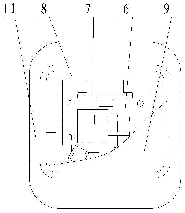
The invention provides a split type photovoltaic terminal box with a cable protection structure. The split type photovoltaic terminal box comprises a left box body assembly, a middle box body assembly and a right box body assembly, and the left box body assembly, the middle box body assembly and the right box body assembly are independent from one another. Conductors and diodes are arranged in the left box body assembly, the middle box body assembly and the right box body assembly, a pressing block is arranged at the lower left corner of a left box body, the included angles between the pressing block and the two side walls of the left box body are 135 degrees, a protection sleeve is arranged on the pressing block, and the lead-out end of a negative electrode cable penetrates through the space between the pressing block and the protection sleeve, and is connected with the conductors. A pressing block is arranged at the lower right corner of a right box body, the included angles between the pressing block and the two side walls of the right box body are 135 degrees, a protection sleeve is arranged on the pressing block, and the lead-out end of a positive electrode cable penetrates through the space between the pressing block and the protection sleeve, and is connected with the conductors. The split structure is adopted in the terminal box, the three box body assemblies are used in cooperation, the length of the cable is reduced, and the internal resistance of a transmission circuit is reduced. The lead-out ends of the cables are designed obliquely, and are suitable for mounting of various assemblies, and the cables are prevented from being twisted. The lead-out ends of the cables are provided with the protection sleeves, and the function of protecting the cables is further achieved.

Description

technical field [0001] The invention belongs to the field of solar photovoltaic applications, in particular to a split-type photovoltaic junction box with a cable protection structure. Background technique [0002] The inexhaustible solar energy is more and more favored by people because of its safety, cleanliness and environmental protection. The solar photovoltaic industry has become a sunrise industry that the world is chasing. In China, more and more companies have joined this "daily enterprise". China has become the third largest photovoltaic manufacturing base in the world, second only to Japan and Germany. At the same time, it also promotes the development of solar-related parts and components industries, such as solar photovoltaic junction boxes, photovoltaic connectors, controllers, inverters, batteries, etc. [0003] As an important part of the solar cell module, the solar photovoltaic junction box is a connector between the solar cell array formed by the solar ce...

Claims


Application Information

Patent Timeline
Patent Type & Authority Applications(China)
IPC IPC(8): H02S40/34
CPCH02S40/00Y02E10/50
Inventor 刘凯赵辉郑加强张灿
Owner 安徽华成电子科技有限公司
Learn More