
Divided conductor clamp fitting for EHV (Extra-High Voltage) DC (Direct Current) convertor station and branch clamps thereof

An ultra-high voltage DC, split wire technology, used in conductive connections, clamping/spring connections, electrical components, etc., can solve the problem of the seam being located outside the branch clamp, etc., to improve the anti-corona performance and ensure the anti-corona performance. , the effect of simple structure

Active Publication Date: 2015-02-18
PINGGAO GRP +1
View PDF6 Cites 15 Cited by
  • Summary
  • Abstract
  • Description
  • Claims
  • Application Information

AI Technical Summary

Problems solved by technology

[0005] The present invention provides a branch line clamp for the split wire clamp fittings of UHV DC converter station to solve the problem that in the prior art, the pressing block of each branch line clamp is arranged outside the corresponding branch line clamp, resulting in a gap between the pressing block and the finger-shaped support body. The technical problem that the seam between them is located on the outside of the branch line clamp; at the same time, the present invention also provides a split wire clamp fitting for UHV DC converter stations using the above branch line clamp

Method used


Image

  • Divided conductor clamp fitting for EHV (Extra-High Voltage) DC (Direct Current) convertor station and branch clamps thereof
  • Divided conductor clamp fitting for EHV (Extra-High Voltage) DC (Direct Current) convertor station and branch clamps thereof
  • Divided conductor clamp fitting for EHV (Extra-High Voltage) DC (Direct Current) convertor station and branch clamps thereof

Examples


Embodiment Construction

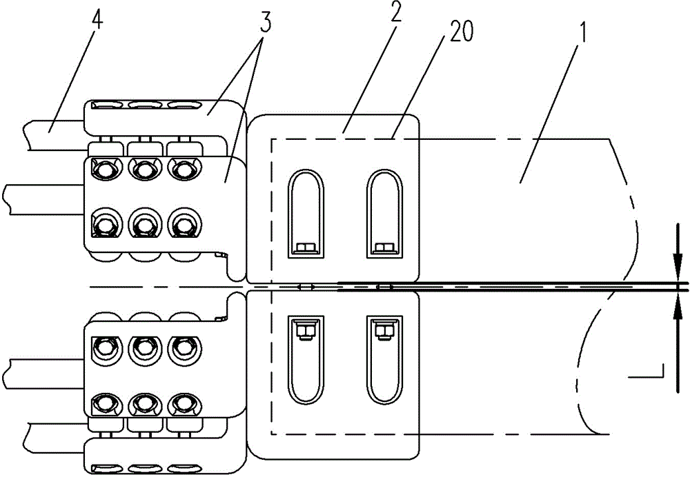
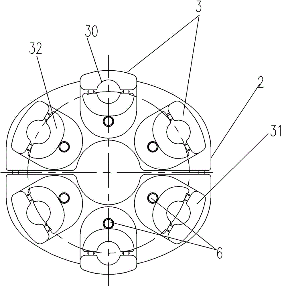
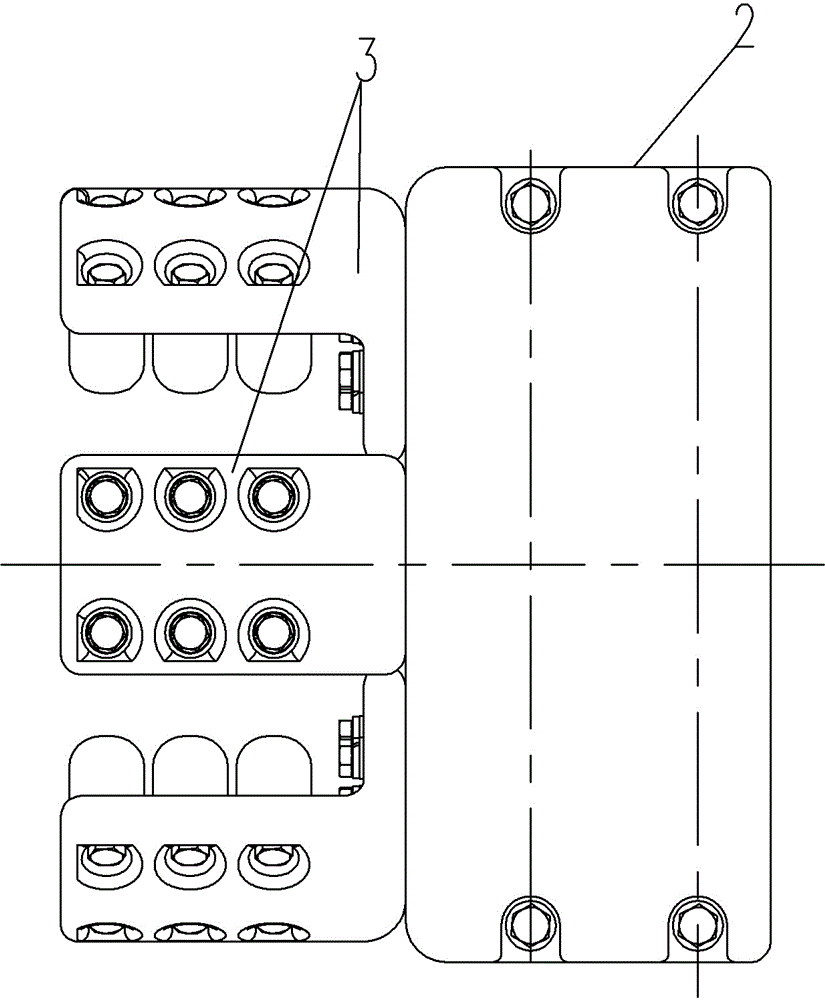
[0037] like Figure 1 to Figure 11As shown, an embodiment of a split wire clamp fitting for an UHV DC converter station, the line clamp fitting in this embodiment includes a busbar clamp 2, and the busbar clamp 2 is provided with a busbar hole 20 for clamping the busbar 1. One end of the busbar clamp 2 extending axially along the busbar hole 20 is fixed with six branch line clamps 3 uniformly distributed around the busbar hole circumferential direction, and each branch line clamp 3 has a coaxial and parallel arrangement with the busbar hole 20 for clamping branch lines 4 The branch line hole 30.

[0038] The bus bar clamp 2 in this embodiment includes two semicircular pipe mother holding clips 25 that are correspondingly assembled together. An installation step 24 is provided, and a bolt hole is correspondingly arranged on the installation step 24, and the connecting bolt 7 is correspondingly inserted into the bolt hole. The two pipe female holding clips 25 respectively have...


PUM


Abstract

The invention provides a divided conductor clamp fitting for an EHV (Extra-High Voltage) DC (Direct Current) convertor station and branch clamps thereof. The clamp fitting comprises a bus-bar clamp, wherein one end of the bus-bar clamp axially extending along a busbar hole is fixedly provided with at least two branch clamps peripherally distributed around the busbar hole; each branch clamp comprises a finger-type support body and a pressing block, a branch hole is defined by the finger-type support body and the pressing block, and the finger-type support body is in an L shape; the finger-type support body is provided with an axial installation section axially extending along the branch hole and a radial installation section which is integrally installed along the radial extending direction of the branch hole or is separately and fixedly arranged on the busbar clamp, the pressing block is located inside the L-shaped finger-type support body and is fixedly arranged on the axial installation section, and the opposite sides of the axial installation section and the pressing block are provided with branch slots for forming the branch holes; the outside parts of the corners of the L-shaped finger-type support bodies are connected in an circular arc transition way, and the pressing blocks on the branch clamps are located inside the corresponding branch clamps toward the central axes of the busbar holes. The clamp fitting is convenient to install and use and good in anticorona.

Description

technical field [0001] The invention relates to a fitting for clamping a split conductor of an ultra-high voltage direct current converter station and a branch clamp thereof. Background technique [0002] At present, most of the equipment clamps for AC substations put into operation in my country are two-split and four-split wire equipment clamps, while the rated capacity and rated current delivered by DC UHV converter stations are relatively large, so equipment clamps with six-split wires are required Meet the requirements of UHV DC converter station. [0003] In the Chinese utility model patent specification whose authorized announcement number is CN203039122U, a wire connection fitting is disclosed, which is used to conduct the corresponding conduction between the pipe busbar and each branch wire. For the busbar hole of the busbar, four branch clamps uniformly distributed around the circumference are arranged on the end of the busbar clamp extending along the axial di...

Claims


Application Information

Patent Timeline
Patent Type & Authority Applications(China)
IPC IPC(8): H01R11/07H01R11/01H01R4/46
CPCH01R4/46H01R11/01H01R11/07
Inventor 宋铁创常林晶徐健涛李俊辉杨国华
Owner PINGGAO GRP
Learn More