Preheating switching device for fuse breaking capacity test

A technology of breaking capacity and switching devices, which is applied in the direction of measuring devices, instruments, fuse testing, etc., can solve the problems of not being able to meet the requirements of automatic monitoring and not reflecting arc characteristics, so as to reduce the risk of burning out, improve the test success rate, and changeover time The effect of small intervals

Inactive Publication Date: 2015-02-18
GANSU ELECTRIC APP RES INST
View PDF6 Cites 5 Cited by
  • Summary
  • Abstract
  • Description
  • Claims
  • Application Information

AI Technical Summary

Problems solved by technology

For the fuse breaking capacity test No.2a, the whole test process takes 30-45 seconds, and for the large-capacity laboratory that realizes the on-off test, the characteristic room of the circuit bears the dynamic stability and heat generated by the large current. Stable, based on the consideration of test cost, the time it bears high current is often limited to less than 10 seconds
The conventional method is to apply the test current at low voltage and high current, and then switch to the high voltage test (large capacity test system) when it is about to break, which cannot meet the 30-45 second requirement of the fuse breaking capacity test No. 2a, while in The long-time high-current device used for temperature rise and characteristic tests in electrical tests cannot meet the requirements of No.2a because it is a low-voltage system and cannot reflect its arc characteristics when the fuse is broken.
[0003] In the 1980s, the state organized relevant units to study the "Research on Preheating Steady Flow and Automatic Switching Device for Fuse Test" ("Sixth Five-Year Plan" scientific and technological research project), and passed the acceptance in 1986. However, with the development of electrical manufacturing technology, This achievement can no longer meet the needs of automated monitoring

Method used


Image

  • Preheating switching device for fuse breaking capacity test
  • Preheating switching device for fuse breaking capacity test

Examples


Embodiment Construction

[0015] The present invention will be described in further detail below in conjunction with the accompanying drawings and specific embodiments.

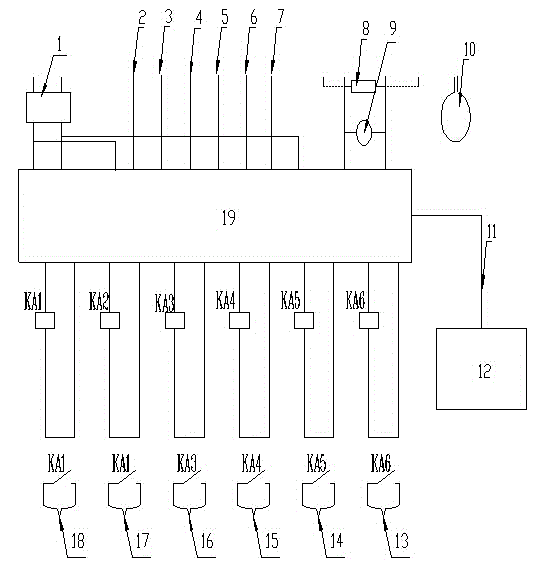
[0016] Such as figure 1 Shown is a preheating conversion device for fuse breaking capacity test, which includes switching power supply 1, programmable controller 19, monitoring / operation computer 12, Rogowski coil + integrator 10, programmable controller 19 and monitoring / The operating computer 12 is connected through the communication cable 11, and the programmable controller 19 is respectively connected with the low-voltage side current step-up limit 2, the low-voltage side current step-down limit 3, the closing indication of the isolation circuit breaker 4, and the opening indication of the isolation circuit breaker 5. High voltage circuit breaker closing indication 6. High voltage circuit breaker opening indication 7. Shunt 8. High voltage circuit breaker opening operation 13. High voltage circuit breaker closing operation 14. Is...


PUM


Abstract

The invention relates to the technical field of electric appliance detection and discloses a preheating switching device for fuse breaking capacity test. The preheating switching device is connected to a large-capacity test system for fuse breaking capacity test, appropriate fuse fusing time is set in a monitoring / operation computer, a test sample (fuse) is mounted, data acquisition of low-voltage current is completed through a shunt by an electrical test data acquisition system, data acquisition of high-voltage current is completed through a Rogowski coil and an integrator by the electrical test data acquisition system, interlocking of a high-voltage breaker and an isolation breaker is realized through a programmable controller, and closing operation of the high-voltage breaker can be started after the isolation breaker is opened. By application of the preheating switching device, the fuse breaking capacity test process is controlled within 30-45 seconds, automatic control is realized, switching time interval of the high-voltage breaker and the isolation breaker is small, test success rate is increased, risk that test equipment is burnt down is lowered, and test cost is lowered.

Description

technical field [0001] The invention relates to the technical field of electric appliance detection, in particular to a preheating conversion device used for a fuse breaking capacity test. Background technique [0002] At the current level of scientific and technological development, the ability of switching electrical appliances cannot be solved by simulation calculation. The development of products must pass the information and experience provided by the large-capacity test station, and finally verify whether it can be finalized and produced through tests. For the fuse breaking capacity test No.2a, the whole test process takes 30-45 seconds, and for the large-capacity laboratory that realizes the on-off test, the characteristic room of the circuit bears the dynamic stability and heat generated by the large current. Stable, based on the consideration of test cost, the time it bears high current is often limited to less than 10 seconds. The conventional method is to apply t...

Claims


Application Information

Patent Timeline
Patent Type & Authority Applications(China)
IPC IPC(8): G01R31/07G01R31/74
Inventor 李平马发翔孙文宝马超明王满军冯立玮
Owner GANSU ELECTRIC APP RES INST
Why Eureka
Try Eureka