Sludge conveying system

A conveying system and sludge technology, applied in transportation, packaging, storage devices, etc., can solve problems such as low construction efficiency, large damage to the surrounding environment, and poor carrying capacity of the backfill area

Inactive Publication Date: 2015-02-18
宁波高新区围海工程技术开发有限公司
View PDF11 Cites 5 Cited by
  • Summary
  • Abstract
  • Description
  • Claims
  • Application Information

AI Technical Summary

Problems solved by technology

[0003] When the cutter-suction blow-fill equipment is working, first use the reamer to add the sludge into the water to fully mix the sludge and water, and then use the suction pump to suck up the diluted sludge. This cutter-suction blow-fill equipment has the following problems : 1) Due to the need to use the reamer to add the sludge into the water, and the reamer is under great pressure, the energy loss is serious; 2) The work of the reamer has great damage to the surrounding environment of the working area; 3) Since the suction is diluted Generally, the sludge content is only 15% to 25%, so the construction efficiency is very low; 4) The natural consolidation time of the diluted sludge sucked up is long; 5) Although the water in the diluted sludge sucked up Generally, it will flow off automatically in the natural environment, but the strength of the silt after dehydration is still not as strong as that of the original silt, resulting in poor bearing capacity of the backfill area formed by using this silt
The production cost and maintenance cost of the piston type earth moving ship are very high

Method used


Image

  • Sludge conveying system
  • Sludge conveying system
  • Sludge conveying system

Examples


Embodiment 1

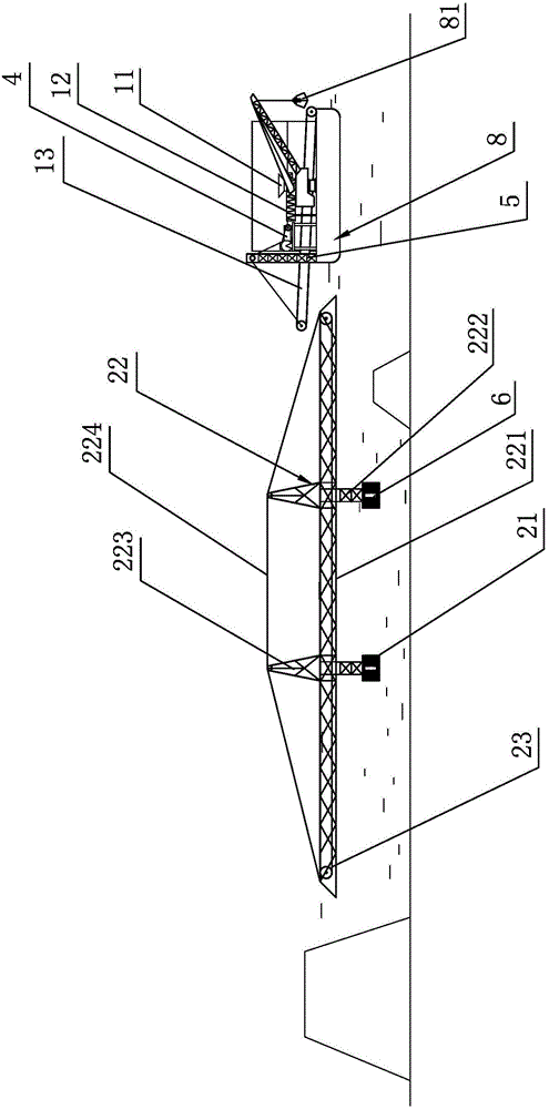
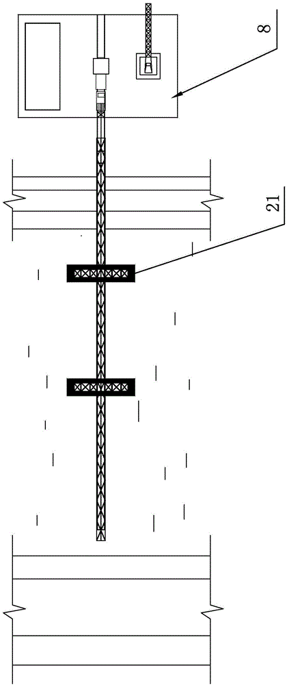
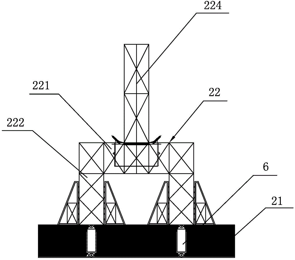
[0027] A kind of sludge conveying system that present embodiment proposes, such as Figure 1 to Figure 3 As shown, it includes a grab dredger 8 working on the water, an auxiliary conveying mechanism arranged on the grab dredger 8 and a main conveying mechanism working in the backfill area. The auxiliary conveying mechanism is conveyed by a hopper 11 and a screw. Conveyor 12 and auxiliary belt conveyor 13, screw conveyor 12 is installed on the grab dredger 8, the feed port of the hopper 11 receives the grab 81 of the grab dredger 8 from the inland beach For sludge, the discharge port of the hopper 11 is connected with the feed port of the screw conveyor 12, the discharge port of the screw conveyor 12 is located directly above the belt of the auxiliary belt conveyor 13, and the head end of the auxiliary belt conveyor 13 is fixed on the grab On the bucket dredger 8, the end of the auxiliary belt conveyor 13, that is, the discharge end, is suspended outside the grab dredger 8, and...

Embodiment 2

[0034] A kind of sludge conveying system that present embodiment proposes, such as Figure 4 As shown, it includes an excavator 9 working on land, an auxiliary conveying mechanism arranged on land, and a main conveying mechanism working in a backfill area. The auxiliary conveying mechanism is composed of a hopper 11 and a screw conveyor 12, and the screw conveyor 12 enters One end of the material is fixed on the land, one end of the discharge of the screw conveyor 12 is suspended, the feed port of the hopper 11 receives the mud grabbed by the grab bucket 91 of the excavator 9, and the discharge port of the hopper 11 is connected with the feed port of the screw conveyor 12. The feed port is connected, and the main conveying mechanism is composed of two flat-bottomed floating bodies 21, steel trusses 22 and main belt conveyor 23. The machine 23 is installed on the steel truss 22, the end of the main belt conveyor 23, that is, the discharge end is located directly above the backf...


PUM


Abstract

The invention discloses a sludge conveying system, which comprises a grab dredger, an auxiliary conveying mechanism and a main conveying mechanism, wherein the grab dredger works on water, the auxiliary conveying mechanism is arranged on the grab dredger, the main conveying mechanism works in a backfilling region, the auxiliary conveying mechanism consists of a hopper, a spiral conveyer and an auxiliary belt conveyor, a feeding opening of the hopper receives sludge grabbed by a grab of the grab dredger, a discharging opening of the hopper is connected with a feeding opening of the spiral conveyer, a discharging opening of the spiral conveyer is positioned right above a belt of the auxiliary belt conveyor, the tail end of the auxiliary belt conveyor is hung outside the grab dredger, the main conveying mechanism consists of a plurality of flat bottom floating bodies, a steel truss and a main belt conveyor, the flat bottom floating bodies are flatly placed on the backfilling region, the steel truss is erected on the flat bottom floating bodies, the main belt conveyor is arranged on the steel truss, the tail end of the auxiliary belt conveyor is positioned right above the belt of the main belt conveyor. The sludge conveying system has the advantages that the automation degree is high, the conveying efficiency can reach 300 to 600m<3> per hour, and the conveying cost is low.

Description

technical field [0001] The invention relates to a conveying machine, in particular to a sludge conveying system, which is suitable for soil conveying in large water conservancy projects. Background technique [0002] In municipal and water conservancy projects, backfilling earthwork is a major technical difficulty in tidal flats, swamps, wetlands and other places where deep silty clay layers are deposited. Conventional land and water equipment are difficult to construct, and the cutter-suction dredging equipment, truss-type tidal flat embankment machine, and piston-type earth-moving ship have been developed for backfilling and earth-moving machinery. [0003] When the cutter-suction blow-fill equipment is working, first use the reamer to add the sludge into the water to fully mix the sludge and water, and then use the suction pump to suck up the diluted sludge. This cutter-suction blow-fill equipment has the following problems : 1) Due to the need to use the reamer to add ...

Claims


Application Information

Patent Timeline
Patent Type & Authority Applications(China)
IPC IPC(8): B65G63/00
Inventor 冯宇余朝伟干焕军张威
Owner 宁波高新区围海工程技术开发有限公司
Why Eureka
Try Eureka