Self-calibration control device of warp knitting machine yarn guide bar

A yarn guide bar and control device technology, applied in the field of mechatronics, can solve the problem of low alignment efficiency, inability to judge the deviation distance and direction of warp knitting yarn guide bars by human eyes, and the technical level and operation experience requirements of alignment personnel. Extremely high and other problems, to achieve the effect of consistent testing standards, precision and stability, and high adjustment efficiency

Active Publication Date: 2015-02-11
JIANGNAN UNIV
View PDF5 Cites 8 Cited by
  • Summary
  • Abstract
  • Description
  • Claims
  • Application Information

AI Technical Summary

Problems solved by technology

[0003] At present, in actual production, the alignment work of warp knitting machine guide bar is manually shaken by the mechanic or jogging the main shaft at slow speed so that the warp knitting guide needle and the groove needle are in the same plane, and it is judged by human eyes in the parking state Whether the gap between the yarn guide needle and the groove needle is reasonable, and fine-tune it step by step in the control system by hand; but when the warp knitting machine is turned on, the warp knitting guide bar is also swinging back and forth while moving left and right. The needle will pass through the plane where the grooved needle is located in an instant, and it is impossible to judge the deviation distance and direction of the warp knitting guide bar by human eyes. At this time, the machine maintenance personnel can only listen to the sound of the needle rubbing with their ears, and use experience to move left and right. The calibration work can only be completed after several attempts of fine-tuning
[0004] Since the alignment accuracy of the warp knitting machine guide bar has a great influence on the production speed of the entire equipment and the quality of the cloth surface, but there is currently a lack of effective testing tools and means, and the judgment is entirely based on the operator's eyes and ears , the technical level and operating experience of the calibration personnel are extremely high, the calibration efficiency is low and the calibration accuracy cannot be guaranteed

Method used


Image

  • Self-calibration control device of warp knitting machine yarn guide bar
  • Self-calibration control device of warp knitting machine yarn guide bar
  • Self-calibration control device of warp knitting machine yarn guide bar

Examples


Embodiment 1

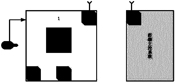
[0017] Such as figure 1 As shown, the terminal control unit 1 of the control device of the present invention obtains the current rotation angle of the main shaft through an absolute encoder 2 installed on the main shaft of the warp knitting machine and rotates synchronously with the main shaft. When the angle value reaches the internal setting angle Nearby, that is, when the yarn guide needle on the guide bar of the warp knitting machine and the groove needle on the needle bed are on the same plane, the microcontroller MCU on the terminal control unit 1 starts the high-definition camera 3 to take pictures of the yarn guide needle facing the groove needle. The arrangement image of the position is directly sent to the image algorithm processing module 4 located on the terminal control unit 1. The image algorithm processing module 4 is composed of a high-speed digital signal processor DSP embedded with a special image processing algorithm, which processes the image and Identify a...

Embodiment 2

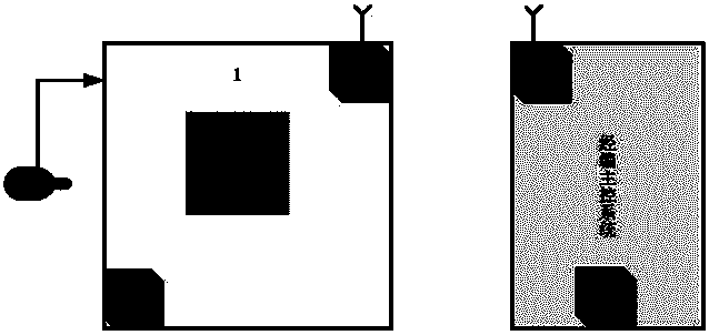
[0020] Such as figure 2 As mentioned above, the control idea of ​​this embodiment is basically the same as that of Embodiment 1, and the difference is mainly reflected in the following two aspects: First, the image algorithm processing module 4 is embedded in the industrial computer of the main control system of the warp knitting machine in the form of a software module run, with the help of the hardware resources of the industrial computer to complete the image processing, extract the deviation direction and deviation distance of the guide needle relative to the groove needle, and directly provide the alignment information to the main control system of the warp knitting machine to complete the guide bar of the warp knitting machine Calibration and fine-tuning; secondly, the terminal control unit 1 no longer includes image algorithm processing, but mainly completes the collection of image data at the time of needle passing, and performs high-speed batching of image data throug...


PUM


Abstract

The invention provides a self-calibration control device of a warp knitting machine yarn guide bar and belongs to the technical field of mechanical-electrical integration. The problem that needling is required to be frequently calibrated by human eyes in the warp knitting machine yarn guide bar which is electronically and transversely driven is solved. The needling camera time of the yarn guide bar is determined by a coder (2) which is arranged on the main shaft of a warp knitting machine and is interconnected with a terminal control unit (1); relative position images of a warp knitting machine yarn guide needle and a slot needle positioned in the same plane at the needling time are acquired through a high-definition camera (3); after being processed by an image algorithm processing module (4), a calibration instruction of the yarn guide bar is given by a wireless data transmission transmitting module (5), and a wireless data transmission receiving module (6) which can be conveniently plugged into a warp knitting main control system receives the instruction and transmits the instruction to the main control system to calibrate the warp knitting machine yarn guide bar. Automatic calibration control on the yarn guide bar in two states, i.e. a halt state and a start state, can be realized without labor participation, and the control precision and the intelligence degree of a warp knitting machine numerical control system can be obviously improved.

Description

technical field [0001] The invention belongs to the technical field of mechatronics, and relates to a warp knitting machine control device, in particular to a warp knitting machine yarn guide bar self-alignment control device. Background technique [0002] After the guide bar of the warp knitting machine is disassembled due to machine debugging, flat needle overhaul, process replacement, machine threading and other reasons, it is necessary to re-align the guide bar, that is, when the guide needle When it is in the same plane as the grooved needles, the guide needles on the warp knitting bar and the grooved needles on the needle bed are evenly arranged one by one, and the distance between the two sides of each guide needle and its left and right adjacent groove needles is required to be The yarn holding gap is equal. [0003] At present, in actual production, the alignment work of warp knitting machine guide bar is manually shaken by the mechanic or jogging the main shaft at...

Claims


Application Information

Patent Timeline
Patent Type & Authority Applications(China)
IPC IPC(8): G05B19/402
CPCD04B27/02G05B19/0428G05B2219/2634
Inventor 张琦蒋高明焦洋夏风林丛洪莲
Owner JIANGNAN UNIV
Why Eureka
Try Eureka